Sponsor Area
Light: Light is a form of electromagnetic radiation (radiant energy) which makes things visible. When the light rays falls on objects, it is reflected back and enters our eyes. This produces the sensation of vision and hence, we are able to see the objects around us.
Important uses of light:
1. Light enables us to see even through a transparent medium because light is transmitted through it.
2. Light makes things around us visible.
2. Light is highly useful in modern communication. We can transmit thousands of telephonic conversations simultaneously via optical fibres over long distances.
In the past there has been a debate over the nature of light. If, it exhibits wave nature or particle nature. And, inorder to establish the nature of light, various theories about the nature of light have been proposed from time to time.
Some of the main theories are as follows:
1. Corpuscular theory of light: Newton, the great among the greatest, proposed in 1675 A.D. that light consists of tiny particles called corpuscles which are shot out at high speed by a luminous object. This theory could explain the reflection, refraction and rectilinear propagation of light.
2. Wave theory of light wave: In 1678, Dutch scientist Christian Huygens, suggested that light travels in the form of longitudinal waves just as sound propagates through air. Later on, Fresnel and Young showed that light propagates as a transverse wave. This successfully explained the reflection, refraction as well as interference, diffraction and polarisation of light waves.
3. Electromagnetic nature of light waves: In 1873, Maxwell suggested that light propagates as electric and magnetic field oscillations. These are called electromagnetic waves which require no medium for their propagation. Also, these waves are transverse in nature.
4. Planck’s quantum theory of light: According to Max Planck, light travels in the form of small packets of energy called photons. In 1905, Albert Einstein used this theory to explain photoelectric effect (emission of electrons from a metal surface when light falls on it).
5. De-Broglie's hypothesis: De Broglie suggested that light has a dual nature, i.e., it can behave as particles as well as waves.
So, we see that in phenomena like interference, diffraction and polarisation, light behaves as a wave while in photoelectric effect, it behaves a particle.
Ray of light: The direction or path along which, light energy travels in a medium is called a ray of light. It is represented by a straight line with an arrow marked on it.
Beam of light: A group of light rays is called a beam of light. A beam of light may be parallel, convergent or divergent.
The below figure shows us the diagram of divergent and convergent beam of light. 
Divergent/ parallel beam of light: The rays from a distant light source (such as the sun) are parallel to each other and they constitute a parallel beam. The rays tend to proceed away from a point.
Convergent beam: rays proceed towards a particular point.
Optical medium: A material through which light can pass is called an optical medium. Optical medium is sort of a transmission medium i.e., a medium of propagation.
On the basis of their behaviour towards light, different media can be classified into three categories:
1. Transparent substances: A substance through which light can be easily transmitted, making the objects to be seen clearly is called transparent substance.
For example, air, water, glass, etc.
2. Opaque substances: A substance which does not allow light to pass through it is called an opaque substance.
For example, wood, metal, stone, etc.
3. Translucent substances: A substance through which light passes only partially and objects are not clearly seen is called a translucent substance.
For example, wax paper, frosted glass, clouds etc.
When light travelling through one medium, falls on the surface of another medium, the following three effects may occur at the surface of separation of the two media:
Reflection: A part of the incident light is bounced back into the first medium. This is called reflection of light.
Refraction: Another part of incident light is transmitted into the second medium and diverges or bends from its path at the surface of separation. This is called refraction of light.
Absorption: The remaining part of incident light is absorbed at the surface of separation. This is called absorption of light.
(i) When light falls on a highly polished surface like mirror, reflection occurs.
(ii) Refraction of light occurs when light falls on a transparent medium like glass or water. When there is diffrence in the density of the medium, a ray tends to bend towards or away from the normal at the interface of media.
When a beam of rays starting from a point source of light suffers a change in direction due to reflection or refraction, and the reflected or refracted rays actually converge or appear to diverge from another point, then the second point is called the optical image of the first point.
For example, when we look into a plane mirror, we see our image behind the mirror. When we look at an object through a telescope, the object is seen much closer than its actual position.
This new position of the object, formed due to reflection or refraction of light, is the optical image of the object.
Real image: If a beam of rays starting from a point source of light, after reflection or refraction, actually converges to a point, then the second point is called the real image of the first.
A real image is formed due to actual intersection of rays, so it can be obtained on a screen.
It is usually inverted.
e.g., The images formed on a cinema screen are real images.
Virtual image: If a beam of rays starting from a point source of light, after reflection or refraction, appears to diverge from another point, then the second point is called the virtual image of the first.
A virtual image is not formed due to the actual intersection of the rays, so it cannot be obtained on a screen.
Virtual image is usually erect.
e.g. The image of our face in a looking glass is a virtual image.
|
Real image |
Virtual image |
|
1. Here the rays actually meet at the point after refraction or reflection. |
1.A virtual image is formed when, the rays appear to converge. |
|
2. Real image can be obtained on the screen. |
2. It cannot be obtained on the screen. |
|
3. Real image is always inverted. |
3. Real image is always erect. |
Mirror is a highly polished and smooth surface to reflect a good fraction of light incident on it. The surface may be metallic or an ordinary glass plate coated with a thin silver layer.
The commonly used mirrors acording to the reflecting mirrors are of three types:
1. Plane mirror
2. Spherical mirror
3. Paraboidal mirror.
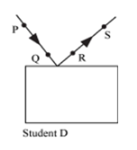
Define the following terms in connection with reflection of light:
Incident ray, reflected ray, point of incidence, normal, angle of incidence and angle of reflection.
Incident ray: The ray of light that falls on the reflecting surface is called incident ray.
Reflected ray: The ray that bounces back from the reflecting surface, after reflection from it is called reflected ray.
Point of incidence: The point at which the incident ray strikes the reflecting surface is called point of incidence.
Normal: The line which is drawn perpendicular to the reflecting surface, at the point of incidence is called the normal at that point.
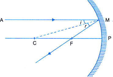
Angle of incidence: It is the angle between the incident ray and the normal to the reflecting surface at the point of incidence. It is denoted reflection by i.
Angle of reflection: It is the angle between the reflected ray and the normal to the reflecting surface at the point of incidence. It is denoted by r.
When a ray of light is incident on a mirror, it gets reflected in accordance with the following laws of reflection:
First law: The incident ray, the reflected ray and the normal at the point of incidence all three, lie in the same plane.
Second law: The angle of incidence (i) is equal to the angle of reflection (r).
i.e., ∠i = ∠r. 
Fig. Reflection in a plane mirror
Properties of images formed by a plane mirrors:
1. The image formed by a plane mirror is virtual and erect.
2. Image formed is of the same size as the object.
3. The image is formed as far behind the mirror as the object is in front of it i.e., object distance is equal to the image distance.
4. Image is laterally inverted i.e., image is inverted sideways with respect to the object.

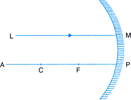
Spherical mirror is a mirror whose reflecting surface is a part of a hollow sphere. The reflecting surface of the spherical mirrors may be curved inwards or outwards.
In Fig, S is a hollow glass sphere being cut by a plane AB. The section LPM of this spherical shell cut by the plane, forms a part of the sphere and is known as spherical surface.
If either side of this spherical surface is silvered, we get a spherical mirror. 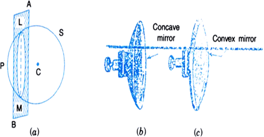
Spherical mirrors are of two types:
(i) Concave mirror: A spherical mirror, whose reflecting surface is curved inwards i.e., towards the centre of the the sphere is called as concave mirror. Concave mirror is silvered on the outer bulged surface and reflects light from the hollow inner surface. Figure (b) shows us a concave mirror.
(ii) Convex mirror: A spherical mirror is convex if it is silvered on the inner hollow surface and reflects light from the outer bulged surface. The reflecting surface of the convex mirror is curved outwards. Figure (c.) shows us the diagram for a convex mirror.
Sponsor Area
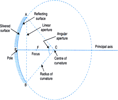
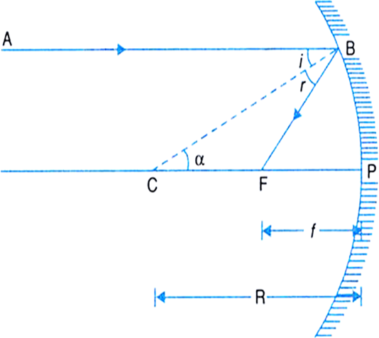
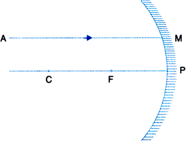
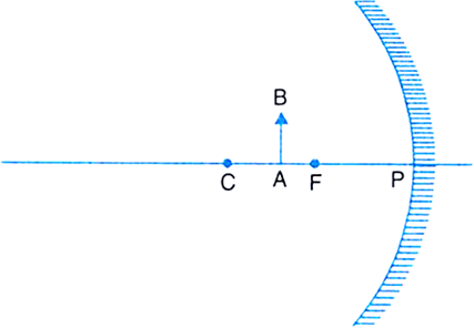
(i) Pole: The centre of the reflecting surface of a spherical mirror is a point which is called the pole. Pole lies on the surface of the mirror.
(ii) Centre of curvature: The centre C of the sphere of which the mirror forms a part is the centre of curvature.
(iii) Radius of curvature: It is the radius R (= AC or BC as shown in the figure) of the sphere of which the reflecting surface of the mirror forms a part.
(iv) Principal axis: The line passing through the pole and the centre of curvature of mirror is called its principal axis.
(v) Linear aperture: It is the diameter AB of the circular boundary of the spherical mirror.
(vi) Angular aperture: It is the angle ACB subtended by the boundary of the spherical mirror at its centre of curvature.
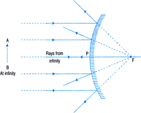
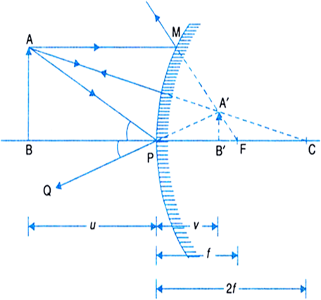
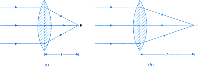
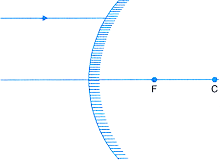
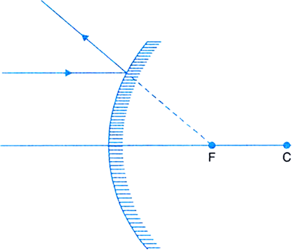
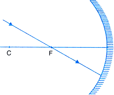
(vii) Principle focus: It is a point F on the principal axis where a beam of light parallel to the principal axis either actually converges to or appears to diverge from, after reflection from a mirror.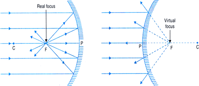
Fig. Principal focus of (a) a concave mirror (b) a convex mirror.
As shown in Fig.(a), when a beam of light is incident on a concave mirror parallel to its principal axis, it actually converges to a point F on the principal axis after reflection. So a concave mirror has a real focus and hence, it is called a converging mirror.
As shown in Fig.(b), when a beam of light is incident on a convex mirror parallel to its principal axis, after reflection, it appears to diverge from a point F (lying behind the mirror) on the principal axis.
So a convex mirror has a virtual focus and hence, it is called a diverging mirror.
(viii) Focal length: The distance f (= PF) between the focus and the pole of the mirror is called the focal length of the mirror.
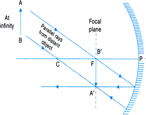
(ix) Focal plane: The vertical plane, passing through the principal focus and which is perpendicular to the principal axis is called focal plane.
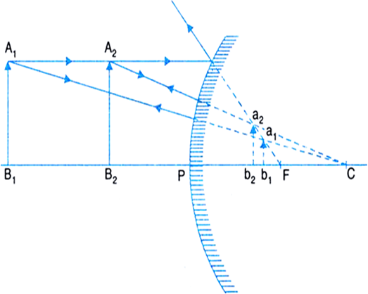
When a parallel beam of light is incident on a concave mirror at a small angle to the principal axis, it is converged to a point in the focal plane of the mirror.
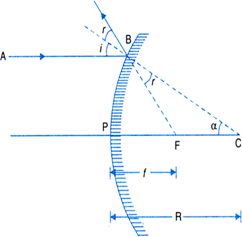
Note: A line joining any point of the spherical mirror to its centre of curvature is always normal to the mirror at that point.
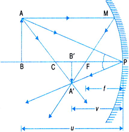
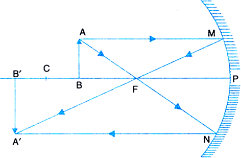
Rules for drawing images formed by spherical mirrors:
The position of the image formed by spherical mirrors can be found by considering any two of the following rays of light coming from a point on the object.
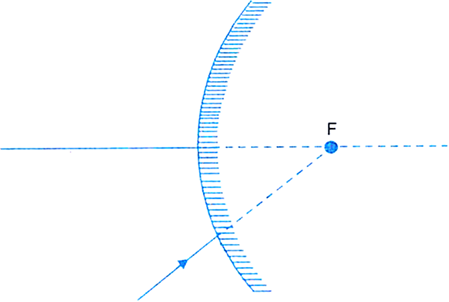
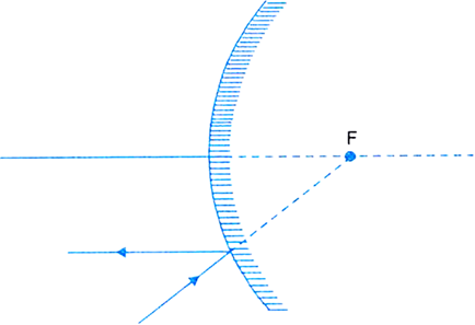
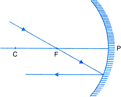
(i) A ray proceeding parallel to the principal axis, after reflection, will pass through the principal focus in the case of a concave mirrors [Fig.(a)], and appear to diverge or come from focus in the case of a convex mirror [Fig.(b)]. 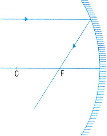
Fig.(a). A ray parallel to the principal axis through F after reflection from a concave mirror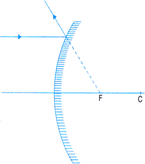
Fig.(b) A ray parallel to the principal axis appears to come from F after reflection from a convex mirror.
(ii) A ray passing through the principal focus in the case of a concave mirror [Fig.(c)], and directed towards the principal focus in the case of a convex mirror will [Fig.(d)], after reflection, pass parallel to the principal axis. 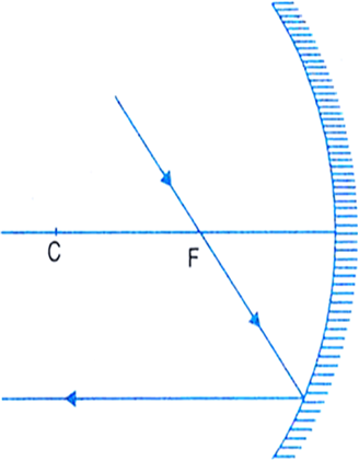
Fig. (c) A ray through F becomes parallel the principal axis after reflection from a concave mirror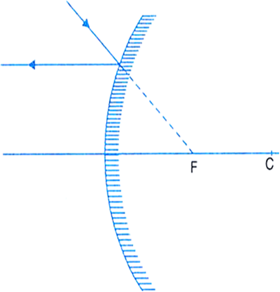
Fig.(d) A ray directed towards F becomes parallel to the principal axis after reflection from a convex mirror
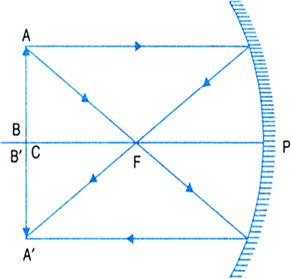
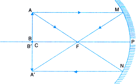
(iii) A ray passing through the centre of curvature in the case of a concave mirror and directed towards the centre of curvature in the case of a convex mirror falls normallly (∠i = ∠r = 0°) and is reflected back along the same path. This is illustrated in fig. (e) and fig. (d).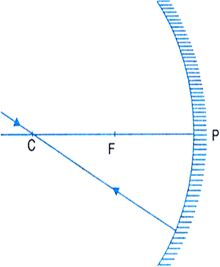
Fig.(e) A ray passing through C is reflected back along of same path after reflection from a concave mirror.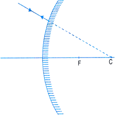
Fig.(F) A ray directed towards C is reflected back along same path after reflection from a convex mirror.
(iv) A ray which is incident obliquely to the principal axis, towards the pole P, on the concave mirror or a convex mirror is reflected obliquely, following the laws of reflection at the point of incidence, i.e., the incident and reflected rays make equal angles with the principal axis. This condition is illustrated in fig.(G).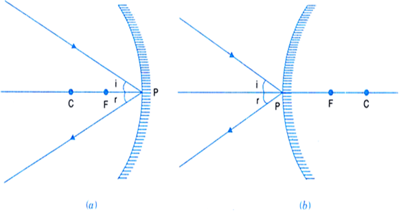
Fig.(G) Incident and relfected rays follow the laws of reflection
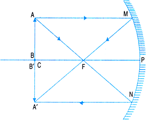
By drawing ray diagrams, explain the formation of image when an object is placed on the principal axis of a concave mirror at the following positions:
(i) At infinity.
(ii) Beyond the centre of curvature.
(iii) At the centre of curvature.
(iv) Between the centre of curvature and the focus.
(v) At the principal focus.
(vi) Between the pole and the focus.


It is desired to obtain an erect image of an object, using a concave mirror of focal length 20 cm.
(i) What should be the range of distance of the object from the mirror?
(ii) Will the image be bigger or smaller than the object.
(iii) Draw a ray diagram to show the image formation in this case.
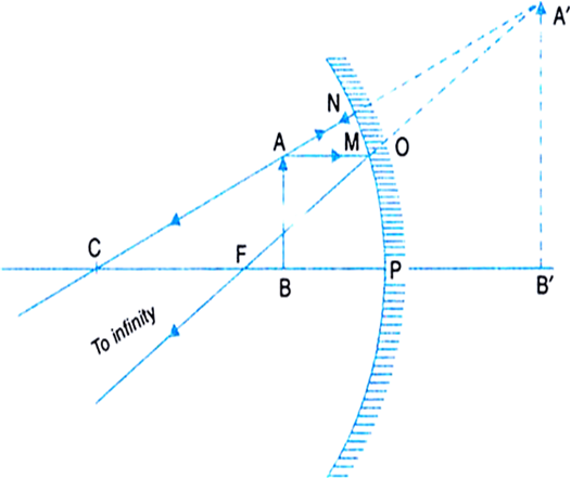
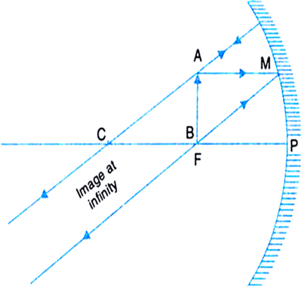
With the help of ray diagrams, explain the formation of images by a convex mirror for the following position of the object:
(i) Object between pole and infinity.
(ii) Object at infinity.
Position of the object | Position of the image | Nature of the image | Size of the image |
1. Between pole P and infinity | Between P and F, behind the mirror | Virtual and erect | Diminished |
2. At infinity | At the focus, behind the mirror | Virtual and erect | Highly diminished, point-sized |
Identification of mirror:
We are given three mirrors. Let's see our faces in each mirror, turn by turn. Initially, keep the face close to the mirror but, slowly move away from the mirror.
1. If the image formed on the mirror is of the same size as our face but laterally inverted (i.e., left face looks right and vice-versa) for all positions, then it is a plane mirror.
2. If the image formed is erect and enlarged initially but gets inverted as the face is moved away, then it is a concave mirror.
3. If the image formed is erect and smaller in size for all positions, then it is a convex mirror.
Uses of concave mirrors:
1. Shaving mirror: A concave mirror is used as a shaving or make-up mirror because it forms erect and enlarged image of the face when it is held closer to the face.
2. As head mirror: E.N.T. specialists use a concave mirror. The light coming from a lamp after reflection from the mirror is focussed into the throat, ear or nose of the patient making the affected part more visible.
3. In ophthalmoscope: It consists of a concave mirror with a small hole at its centre. The doctor looks through the hole from behind the mirror while a beam of light from a lamp reflected from it is directed into the pupil of patient’s eye which makes the retina visible.
4. In headlights: Concave mirrors are used as reflectors in headlights of motor vehicles, railway engines, torch lights, etc. The source is placed at the focus of the concave mirror. The light rays after reflection travel over a large distance as a parallel beam of high intensity.
5. In astronomical telescopes: A concave mirror of large diameter (5 m or more) is used as objective eyepiece in an astronomical telescope. It collects light from the sky, and makes visible even those faint stars which cannot be seen with naked eye.
6. In solar furnaces: Large concave mirrors are used to concentrate sunlight to produce heat in solar furnace.
Uses of convex mirrors:
Drivers use convex mirror as a rear-view mirror in automobiles because of the following two reasons:
1. A convex mirror always forms an erect, virtual and diminished image of an object placed anywhere in front of it.
2. A convex mirror has a wider field of view than a plane mirror of the same size.
Thus convex mirrors enable the driver to view much larger traffic behind him than would be possible with a plane mirror.
The main disadvantage of a convex mirror is that it does not give the correct distance and the speed of the vehicle approaching from behind.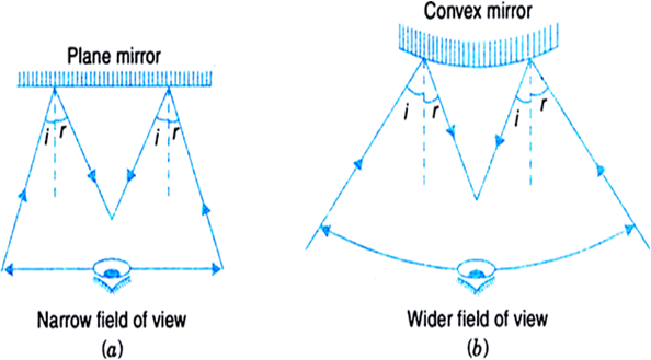
Fig. Field of view of (a) a plane mirror (b) a convex mirror
Given,
Radius of curvature, R = 20 cm
Relationship between radius and focal length is as :
Focal length =
is the focal length of the mirror.
Why do we prefer a convex mirror as a rear-view mirror in vehicles?
Convex mirrors are used as rear-view mirror in vehicles because of the following two reasons:
1. A convex mirror always forms an erect, virtual and diminished image of an object placed anywhere in front of it.
2. A convex mirror has a wider field of view than a plane mirror of the same size. Thus, convex mirrors enable the driver to view much larger traffic behind him than would be possible with a plane mirror.
The disadvantage of a convex mirror is that it does not give the correct distance and hence, the speed of the vehicle approaching from behind cannot be estimated precisely. 
The Fig. above shows the field of view of (a) a plane mirror (b) a convex mirror.
New cartesian sign convention for reflection by spherical mirrors:
1. The object is always placed on the left side of the mirror.This implies that the incident light from the object falls from the left-hand side from the mirror.
2. All the distances parallel to the principal axis are measured from the pole of the mirror.
3. All distances measured in the direction of incident light (measured to the right of origin) are taken as positive.
4. All distances measured in the opposite direction of incident light (measure to the left of the origin) are taken as negative.
5. Distances measured upwards and perpendicular to the principal axis are taken positive.
6. Distances measured downwards and perpendicular to the principal axis are taken negative. 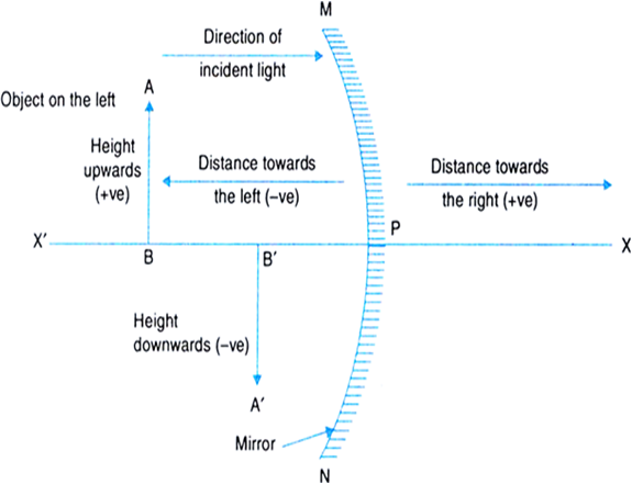
Fig. New cartesian sign convention for reflection of light by spherical mirrors
New cartesian sign convention:
The pole P of the spherical mirror is taken as the origin and the principal axis of the mirror is along the X-axis of the coordinate system.
Keeping this in mind, we can easily note the following facts:
(i) Object distance, u is always taken negative, because the object is placed on the left of the mirror.
(ii) In case of a concave mirror, a real image is formed in front (left side) of the mirror and a virtual image is formed behind (right side) the mirror, so image distance v is negative for a real image and positive for a virtual image.
(iii) In case of a convex mirror, the image distance v is always positive because the image is formed behind the mirror and is virtua.
(iv) The object height h is always taken positive, because the object is placed above the principal axis.
(v) The image height h' is taken negative for real image (as it lies below the principal axis) and the image height h' is taken positive for a virtual image (as it lies above the principal axis).
(vi) The focal length and radius of curvature of a concave mirror are taken negative because the principal focus lies on the left of the mirror.
(vii) The focal length and radius of curvature of a convex mirror are taken positive, because the principal focus lies on the right hand side of the mirror.

Size of the image in the upward direction, A' B' = + h'
Size of the object in the upward direction, AB = + h
Image distance from right, PB' = + v
Object distance from left, BP = - u
A' B' P and ABP, we get
Magnification,
Therefore, linear magnification in terms of u and f can be expressed using the mirror formula.
Thus, we have
Linear magnification in terms of v and f is also found using the mirror formula.
Therefore, we have
Hence, for any spherical mirror, concave or convex, we have
Magnification,
is the required expression.
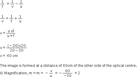
We are given a concave mirror.
Here,
Object size, h = + 5.0 cm
Object distance, u = - 25 cm
Radius of curvature, R = - 30 cm [R is -ve for a concave mirror]
Therefore,
Focal length,
Now, using the mirror formula,
we have,
i.e.,
Magnification,
Image size,
As v is (-)ve, so a real, inverted image of height 7.5 cm is formed at a distance of 37.5 cm in front of the mirror.
Sponsor Area
We are given a concave mirror.
Here,
Object size, h = + 4.0 cm
Object distance, u = -25.0 cm
Focal length, f = - 15.0 cm
Image distance, v = ?
Image size, h' = ?
Now, using the mirror formula,
The screen should be placed at a distance of 37.5 cm on the object side of the mirror, to obtain a sharp image of the object.
Magnification,
Image size,
The image formed is real, inverted (because h' is negative) and enlarged in size.
We are provide with a concave mirror.
Here,
Size of the object, h = + 2 cm
Object distance, u = - 30 cm
Focal length, f = -15 cm
Now, using the mirror formula,
we have therefore,
i.e.,
Thus, the screen should be placed at 30 cm in front of the mirror so as to obtain the real image.
Magnification,
Therefore,
Image size, h',
The image formed is real, inverted and is of the same size as the object.
The image formation is shown in the ray diagram given below.
Given, a convex mirror.
We have,
Radius of curvature, R = + 3.00 m [R is +ve for a convex mirro]
Object distance, u = - 5.00 m
Image distance, v = ?
Height of the image, h' = ?
Therefore,
Focal length,
Using the mirror formula,
The image is formed at a distance of 1.15 m behind the mirror.
Now,
Magnification,
The image is virtual, erect and smaller in size by a factor of 0.23.
Given, a convex mirror.
We have,
Radius of curvature, R = +3.00 m [R is +ve for a convex mirror]
Object distance, u = - 4.5 m
Image distance, v = ?
Image size, h' = ?
Using the relationship between focal length and radius of curvature, we have
Focal length, [ f is +ve for a convex mirror]
Using the mirror formula,
Image distance,
The image is formed at a distance of 9/8 m behind the mirror.
Magnification,
The image formed is virtual, erect and smaller in size by a factor of 0.25 (one-fourth) than the object.
We are given a concave mirror.
So, focal length, f = - 20 cm
Also given the image formed is three times the size of the object.
(a) When the image formed is real:
Given,
Magnification,
Image distance,
Now, using the mirror formula,
we have,
is the object distance measured from the left side of the mirror.
(b) When the image formed is virtual:
Magnification,
Image distance,
Now, using the mirror formula,
we have,
Therefore, the two possible distance of objects from the mirror are 26.67 cm and 13.33 cm from the left side.
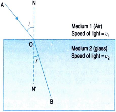
Refraction of light: The phenomenon of bending of light from its straight line path as it passes obliquely from one transparent medium to another is called refraction of light.
The path of the ray of light in the first medium is called incident ray.
The path of the ray of light in the second medium is called refracted ray.
The angle between the incident ray and the normal at the surface of separation is called angle of incidence (i).
The angle between the refracted ray and the normal at the surface of separation is called angle of refraction (r).
Whenever a ray of light passes from one medium another, the following three situations are possible: 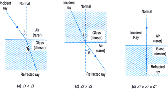
Fig.Refraction of light
(i) When a ray of light passes from an optically rarer medium to a denser medium, it bends towards the normal and angle of refraction (∠r) < angle of incidence (∠i), as shown in Fig.(a).
(ii) When a ray of light passes from an optically denser to a rarer medium, it bends away form the normal and angle of reflection(r) > (i) as shown in Fig.(b).
(iii) A ray of light travelling along the normal passes undeflected. Here ∠ i = ∠ r = 0°.
Laws of refraction of light:
1. The incident ray, the refracted ray and normal to the surface of separation at the point of incidence, all the three, lie in the same plane.
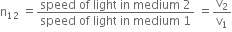
2. For a given pair of media, the ratio of the sine of the angle of incidence and the sine of the angle of refraction is constant.
Mathematically,
The ratio n21 is called refractive index of the second medium with respect to the first medium.
The second law of refraction is also called Snell’s law of refraction.
The refractive index of any medium gives the ratio of the speed of light in vacuum to the speed of light in that medium.
For example, the refractive index of water, nw = 1.33.
This means that the ratio of the speed of light in vacuum or air to the speed of light in water is 1.33.
The refractive index of a medium is dependent on the following factors:
(i) Nature of the medium,
(ii) Nature of the surrounding medium,
(iii) Wavelength of light used, and
(iv) Temperature.
The ability to refract light is represented by the optical density of a medium. A medium having larger refractive index is called optically denser medium. The other medium having lower refractive index is called optically rarer medium.
The speed of light is higher in a rarer medium as compared to than in a denser medium. That is the reason, a ray of light travelling from a rarer medium to a denser medium slows down and bends towards the normal. When the ray travels from a denser medium to a rarer medium, it speeds up and bends away from the normal.
Table: Refractive indices of some material media (with respect to vacuum)
|
Material medium |
Refractive index |
Material medium |
Refractive index |
|
Air |
1.0003 |
Crown glass |
1.52 |
|
Ice |
1.31 |
Canada Balsam |
1.53 |
|
Water |
1.33 |
Rock salt |
1.54 |
|
Alcohol |
1.36 |
Carbon disulphide |
1.63 |
|
Kerosene |
1.44 |
Dense flint glass |
1.65 |
|
Fused quartz |
1.46 |
Ruby |
1.71 |
|
Turpentine oil |
1.47 |
Sapphire |
1.77 |
|
Benzene |
1.50 |
Diamond |
2.42 |
Find out, from the given table, the medium having highest optical density. Also find the medium with lowest optical density.
Refractive indices of some material media (with respect to vacuum)
|
Maierial medium |
Refractive index |
Material medium |
Refractive index |
|
Air |
1.0003 |
Crown glass |
1.52 |
|
Ice |
1.31 |
Canada Balsam |
1.53 |
|
Water |
1.33 |
Rock salt |
1.54 |
|
Alcohol |
1.36 |
Carbon disulphide |
1.63 |
|
Kerosene |
1.44 |
Dense flint glass |
1.65 |
|
Fused quartz |
1.46 |
Ruby |
1.71 |
|
Turpentine oil |
1.47 |
Sapphire |
1.77 |
|
Benzene |
1.50 |
Diamond |
2.42 |
Optical density has a direct dependance on refractive index. The more optically dense a material is, slower it will move through the material.
From the table given, diamond has highest refractive index = 2.42, and so it has largest optical density.
Air has lowest refractive index = 1.0003, so it has lowest optical density.
Note: The refractive index of a material is the number of times slower the light wave will propagate in the material, than it is in the vacuum.
|
Maierial medium |
Refractive index |
Material medium |
Refractive index |
|
Air |
1.0003 |
Crown glass |
1.52 |
|
Ice |
1.31 |
Canada Balsam |
1.53 |
|
Water |
1.33 |
Rock salt |
1.54 |
|
Alcohol |
1.36 |
Carbon disulphide |
1.63 |
|
Kerosene |
1.44 |
Dense flint glass |
1.65 |
|
Fused quartz |
1.46 |
Ruby |
1.71 |
|
Turpentine oil |
1.47 |
Sapphire |
1.77 |
|
Benzene |
1.50 |
Diamond |
2.42 |
Noting down the refractive index of these medium, we have
For kerosene, refractive index, n = 1.44
For turpentine oil, refractive index, n = 1.47
For water, refractive index, n = 1.33
Since water has lowest refractive index, so light travels fastest in this optically rarer medium than kerosene and turpentine oil.
Discuss the refraction through a rectangular glass slab and show that the emergent ray is parallel to the incident ray but laterally displaced. How does lateral displacement depend on the thickness of the glass slab?
Or
With the help of a ray diagram, show that when light falls obliquely on a side of rectangular slab, the emergent ray is parallel to the incident ray.
Show the lateral displacement of the ray on the diagram.
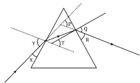
Refraction through a rectangular glass slab:
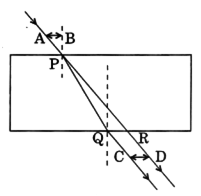
Consider a rectangular glass slab PQRS, as shown in figure below. On the face PQ, a ray AB is incident at an angle of incidence i1. It bends towards the normal, on entering the glass slab, and travels along BC inclined at an angle of refraction r1. The refracted ray BC is incident on the face SR at an angle of incidence i2. The emergent ray CD bends away from the normal at an angle of refraction r2.
Now, using Snell’s law, we have
Refraction from air to glass at face PQ,
...(1)
where,
na is the refractive index of sir and
ng is the refractive index of glass. 
Fig. Refraction through a glass slab
Using Snell’s law for refraction from glass to air at face SR, we have
But
Therefore,
...(2)
Multiplying equations (1) and (2), we get
i.e.,
Thus, the emergent ray CD is parallel to the incident ray AB, but it has been laterally displaced by a perpendicular distance CN with respect to the incident ray. This lateral shift in the path of light on emerging from a medium with parallel faces is called lateral displacement.
It is found that the lateral displacement is directly proportional to the thickness of the glass slab.
Lateral displacement of an emergent ray depends on:
(i) Angle of incidence,
(ii) Thickness of the glass slab, and
(iii) Refractive index of the slab material.
Given,
Refractive index of glass plate, ng = 1.5
Wavelength of light in vacuum, λv = 750 nm = 750 × 10-9 m
Velocity of light in vacuum, c = 3 × 10⁸ ms-1
Frequency of light in vacuum,
For the light refracted in glass, frequency v remains unchanged but, wavelength and speed changes.
(i) Frequency of light in glass = Frequency of light in vacuum
(ii) Velocity of light in glass,
(iii) Wavelength of light in glass,
Given,
Refractive index of ice, ni = 1.31
Refractive index of rock salt, ns = 1.54.
Refractive index of rock salt with respect to ice,
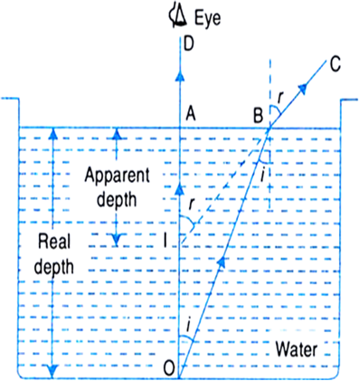
Given,
Refractive index of the liquid, = 1.3
Apparent depth of the object = 7.7 cm
Refractive index =
Therefore,
Lens: A lens is a piece of a transparent, refracting medium bounded by two surfaces, of which one is atleast a curved surface.
The commonly used lenses are the spherical lenses, which have either both surfaces spherical or one spherical and the other a plane one.
Spherical lenses are of two main types:
(i) Convex or converging lens: A lens which is thicker at the centre than at the edges is called a convex lens. It converges a parallel beam of light on refraction through it and has a real focus. 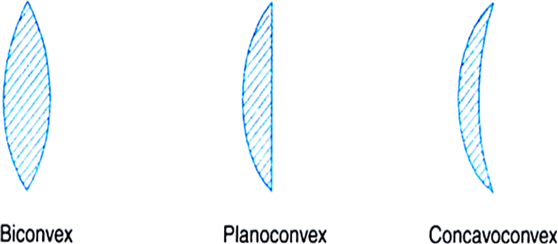 Fig. Different types of convex lenses
Types of convex lenses:
(a) Double concave or biconcave lens: Both the surfaces of these lenses are concave. It is simply called a concave lens.
(b) Plano-concave lens: One surface of this lens is concave and the other side is plane.
(c) Convexo-concave: A lens whose one surface is concave and the other is convex.
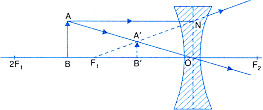
(ii) Concave or diverging lens.
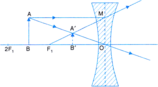
The lens which is thinner at the centre than at the edges is called a concave or diverging lens. It diverges a beam of light on refraction through it or we can say a ray of light which is incident on the surface of the mirror, appears to converge after refraction. Hence, it has a virtual focus. 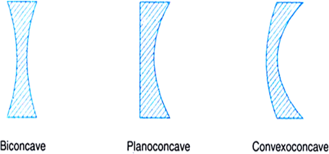
Fig. Different types of concave lenses
Types of concave lenses:
(a) Double concave or biconcave lens: Both the surfaces are concave. It is simply called a concave lens.
(b) Plano-concave lens: One surface of this lens is concave and the other is plane.
(c) Convexo-concave: The lens having one surface as concave and the other convex.
Define the following terms in connection with spherical lenses:
(i) Centre of curvature (ii) Radius of curvature (iii) Principal axis (iv) Principal focus (v) Optical centre (vi) Focal length (vii) Aperture.
(i) Centre of curvature (C): The centre of the sphere, of which the spherical lens forms a part is called as the centre of curvature. It is represented by the alphabet C. Since a lens has two surfaces, so it has two centres of curvature (C1, C2).
(ii) Radius of curvature (R): The radius of the sphere of which the lens forms a part is known as the radius of curvature. Is is symbolised as R.
(iii) Principal axis (C1C2): The line passing through the centre of curvature of the lens is the principal axis. 
Fig. Characteristics of (a) convex lens (b) concave lens
(iv) Principal focus (F): A narrow beam of light which is incident parallel to the principal axis either converges to a point or appears to diverge from a point on the principal axis after refraction through the lens. This point is called principal focus.
All lenses have two principal focii.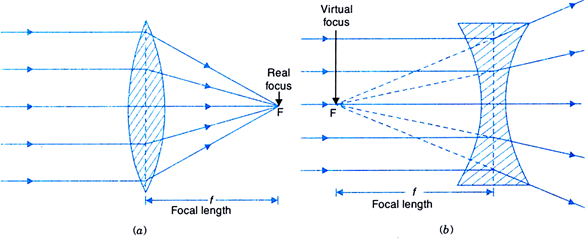
Fig. Principal focus of (a) convex lens (b) concave lens.
(v) Optical centre (O): A point situated within the lens through which a ray of light passes undeviated.
(vi) Focal length (f): Distance between the principal focus and the optical centre of the lens.
(vii) Aperture: The diameter of the circular boundary of the lens is called the aperture of the lens.

|
Convex lens |
Concave lens |
|
1. It is thicker at the centre than at the edges. |
1. It is thinner at the centre than at the edges. |
|
2. It converges a parallel beam of light after refraction through it. |
2. It diverges a parallel beam of light on refraction through it. |
|
3. It has a real focus. |
3. It has a virtual focus. |
Rules for image formation by spherical lenses:
The position of the image formed by any spherical lens can be found by considering any two rays of light coming from a point on the object.
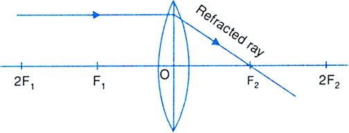
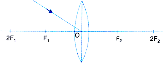
(i) A ray from the object, parallel to the principal axis, after refraction passes through the second principal focus F2 [in a convex lens, as shown in Fig.(a)] or appears to diverge [in a concave lens, as shown in Fig.(b)] from the first principal focus F1.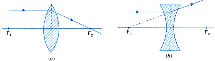
Fig. Path of ray incident parallel to the principal axis of (a) convex lens (b) concave lens.
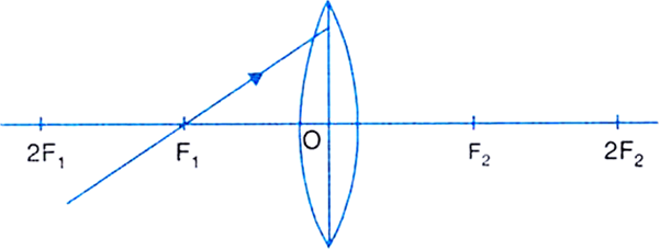
(ii) A ray of light passing through the first principal focus [in a convex lens, as shown in Fig. (a)] or appearing to converge at the focus [in a concave lens, as shown in (b)] emerges parallel to the principal axis after refraction. 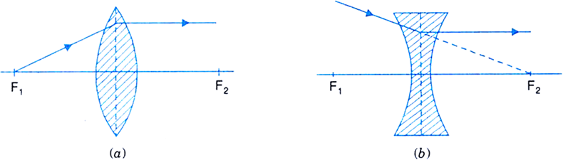
Fig. Path of a ray passing through focus of (a) convex lens (b) concave lens
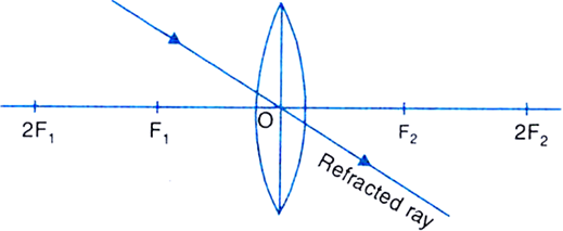
(iii) A ray of light, passing through the optical centre of the lens, after refraction, emerges without any deviation. The figure below illustrates the ray diagram.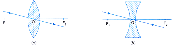
Fig. Path of a ray passing through the optical centre of (a) convex lens (b) concave lens
Image formation by a convex lens:
The following figures below illustrates the formation of image of a convex lens after refraction has taken place.
(i) When object is at infinity:
The image formed is at focus, real, inverted and highly diminished. 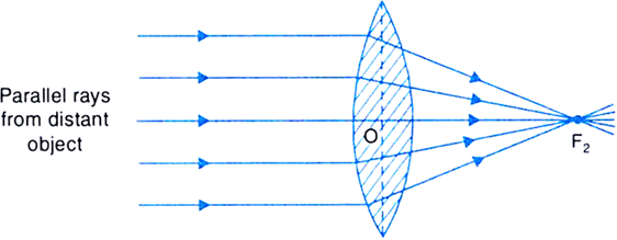
Fig.(a). Image formed by a convex lens when object is at infinity
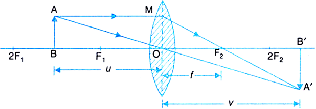
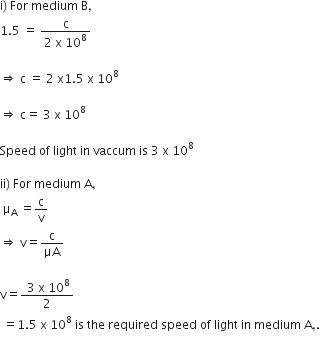
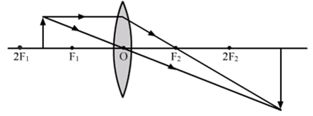
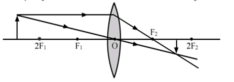
(ii) Object beyond 2F1: The image formed is between F2 and 2F2 on the other side of the lens. The image formed is real, inverted and diminished. 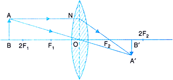
Fig.(b). Image formed by convex lens when object is beyond 2F1
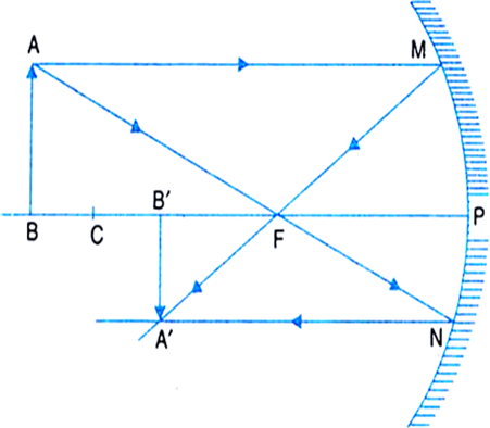
(iii) Object at 2F1: The image formed is at 2F2 and is real and inverted. The image formed is same size as that of the object. 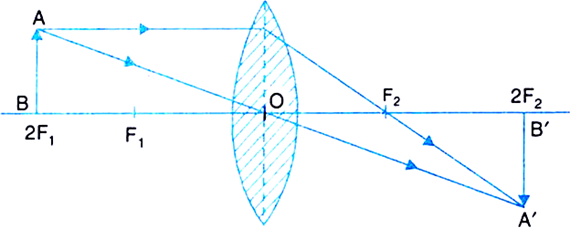
Fig.(c) Image formed by a convex lens when object is at 2F1.
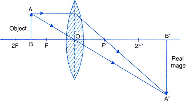
(iv) Object between F1 and 2F2: The image formed beyond 2F2 is real, inverted and magnified. 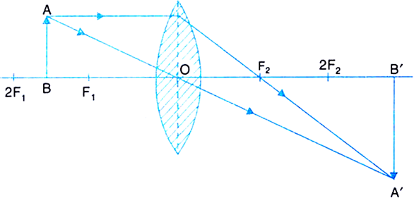 Fig.(d) Image formed by a convex lens when object is between F1 and 2F1.
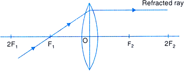
(v) Object at F1: The image formed is real, inverted, highly enlarged and at infinity.
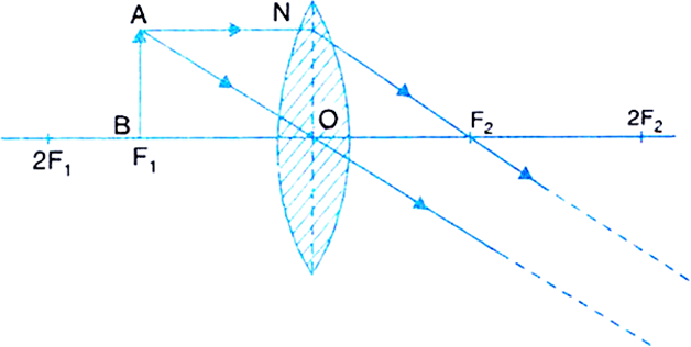
Fig.(e) Image formed by a convex lens with object at F1.
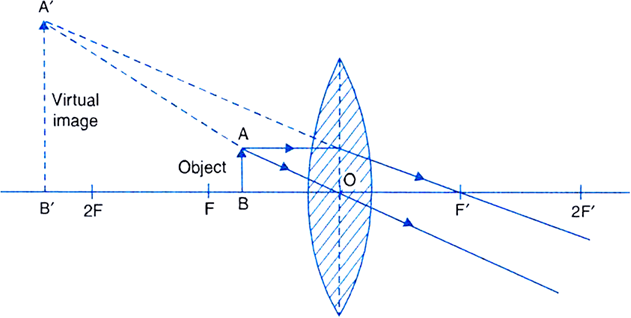
(vi) Object between focus F1 and O: The image is formed on the same side as that of the object and is virtual, erect and enlarged. 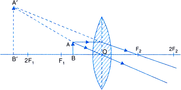
Fig.(f) Image formed by a convex lens when object is between F1 and O
With the help of ray diagrams, explain the formation of images by a concave lens for the following positions of the object:
(i) Object at infinity
(ii) Object between infinity and optical centre O of the lens.

According to the new cartesian sign convention for refraction of light through spherical lenses: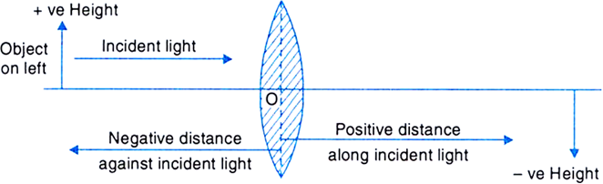
Fig. New cartesian sign convention for a lens
(i) All distances are measured from the optical centre of the lens.
(ii) The distances which are measured in the same direction as that of the incident light are taken positive.
(iii) The distances measured, in the direction opposite to the direction of incident light are taken negative.
(iv) Distances measured upwards and perpendicular to the principal axis are taken as positive.
(v) Distances measured downwards and perpendicular to the principal axis are taken negative.
Rules of new cartesian sign convention:
(i) The focal length of a convex lens is positive and that of a concave lens is negative.
(ii) Object distance u is always negative as it is on the left side of the mirror.
(iii) The distance of real image is positive and that of virtual image is negative.
(iv) The height of the object h is always positive. Height h', of virtual and erect image is positive and that of real and inverted image is negative.
(v) The linear magnification, m = h'/h is positive for a virtual image and negative for a real image.
Sponsor Area
(i) Magnification is positive for a virtual image formed by a lens.
(ii) Magnification is negative for a real image formed by a lens.
Convex and concave lens can be distinguished by touching them. If the curved surface is bulging outwards then it's convex lens and if the curved surface is curved inwards then it's concave lens.
Another way to differentiate between the two lenses is, by bringing some written matter just in front of both the lenses one by one and, look for its image from the other side of the lenses.
(i) If the image of the written matter formed by the lens is virtual, erect and enlarged, then it is a convex lens.
(ii) If the image formed is virtual, erect but diminished, then it is a concave lens.
Given a convex lens.
Here,
Focal length, f = +25 cm.
Image distance, v = + 75 cm
By lens formula,
i.e.,
The object is at 37.5 cm from the lens and the image is real and inverted.
Given,
Size of the object, h = + 3 cm
Object distance, u = - 15 cm
Focal length, f = + 10 cm [f is +ve for a convex lens]
By lens formula,
i.e., Image distance,
Magnification,
Image size,
As v is +ve and h' is negative, so a real and inverted image is formed at 30 cm behind the lens.
We are given a convex lens.
Here,
Object size, h = + 5 cm
Focal length, f = +20 cm [f is +ve for a convex lens]
Object distance, u = -30 cm
Image distance, v = ?
Image size = ?
For a lens using the lens formula,
i.e., Image distance,
Magnification,
Also, Image size,
The positive sign of v shows that the image is formed at a distance of 60 cm to the right of optical centre of the lens. Negaticve sign of h' implies that the image formed is inverted.
Therefore, the image is real and inverted.
Thus, a real and inverted image which is 10 cm tall, is formed at a distance of 60 cm on the right side of the lens.
The image is two times enlarged in size than the object.
Given, a convex lens.
Size of the object, h = + 2 cm
Object distance, u = -32 cm
Image distance, v = 64 - 32 = + 32 cm [v is +ve for a real image]
Now, using the lens formula,
Focal length of the lens, f = + 16 cm.
Magnification, m =
Image size,
The negative sign of the image implies that the image is inverted and since the image distance, v is positive it is real.
The ray diagram below shows us how the image is formed after refraction by the lens: 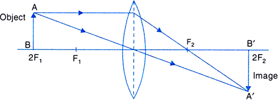
Given,
Onject distance, u = - 60 cm
Image distance, v = -20 cm
Focal length, f = ?
Now, using the lens formula,
i.e., focal length,
Hence, the lens is a diverging less with focal length of 30 cm.
Relation between focal length and power is given by,
P =
(i) Focal length of a converging lens is positive therefore, power of the lens is also positive.
(ii) The power of diverging lens is negative because its focal length is negative.
Combination of lenses is used in various optical instruments because:
(i) To increase the magnification of the image.
(ii) To increase the sharpness of the image.
(iii) To make the final image erect.
(iv) To minimise certain defects or aberrations in the image formed by a single lens.
Given,
Power of the lenses,
Power of combination,
Thus, focal length of combination of lens,
Given, two lenses.
(i) Here,
Power, P = + 2D
Focal length,
Since, the focal length is positive, the lens is convex.
(ii) Here,
Power, P = - 4D
Focal length,
Negative sign of the focal length implies that the lens is concave.
Given,
Focal length of the combination of lens, f = 80 cm = 0.80 m
Power of the lens,
Power of the combination o fthe lens,
Given,
Angle of incidence = 90o - 35o = 55°
Therefore,
Angle of reflection = 55°.
Here,
Angle between incident and reflected ray = 80o
i.e., 2i = i + r = 80°
Therefore,
Deviation = 180° - 2i
= 180° - 80°
= 100°.
When a person moves towards a mirror, his virtual image also moves towards the mirror by equal distance.
Relative speed of man and his image = 2 × Speed of man towards the mirror
= 2 × 5
= 10 m/s.
Sponsor Area
Given,
Radius ofcurvature, R = 1 m
Focal length, f =
(i) The upper part of the mirror is convex because the image appears diminished than it's actual size.
(ii) The middle part of the mirror is concave as, an enlarged image is formed.
(iii) The lower part of the mirror is plane because there is no change in the size of the image.
Convex mirrors are used in automobiles to see the traffic from behind due to two reasons:
(i) Convex mirrors always forms erect and diminished image.
(ii) It has large and wider field of view.
Here, since the ray of light is incident along the principal axis, angle of incidence = 0°
∴ Angle of reflection = 0°.
Principal focus is a point on the principal axis where the rays which are incident parallel to the principal axis meet after reflection.
Principal focus is a point on focal plane and is located on the principal axis.
Focus is a point where rays parallel to each other meet. It is not necessary for the rays to be parallel to the principal axis.
These are infinite foci, all lying in a plane called focal plane.
(i) A concave mirror has a real focus.
(ii) A convex mirror has a virtual focus.
The refractive index of a medium depends on the following factors:
(i) nature of the medium,
(ii) wavelength of light,
(iii) temperature and
(iv) nature of the surrounding medium.
(i) Refractive index is minimum for vacuum (n = 1).
(ii) Refractive index is maximum for diamond (n = 2.42)
N here denotes the refractive index.
Refractive index of a medium is inversely proportional to the speed of light in that medium.
(i) Speed of light is maximum in medium A for which n (= 1.33) is minimum.
(ii) Speed of light is minimum in medium D for which n (= 1.65) is maximum.
n is the refractive index.
The following table gives the values of refractive indices of a few media:
|
S. No. |
1 |
2 |
3 |
4 |
5 |
|
Medium |
Water |
Crown glass |
Rock salt |
Ruby |
Diamond |
|
Refractive index |
1.33 |
1.52 |
1.54 |
1.71 |
2.42 |
Use this table to give an example of (i) a medium pair so that light speeds up when it goes from one of these media to another. (ii) a medium pair so that light slows down when it goes from one of these media to another.
When the ray of light travels from a denser (high refractive index) to rarer medium (low refractive index), speed of light ray speeds up. When light ray travels from rarer to denser medium it's speed slows down.
Therefore,
(i) Light speeds up when the ray propagates from crown glass to water.
(ii) Light slows down when it travels from water to diamond.

Total power of combination = + 6D + 2D = +8D.
Since power of the combination of lenses increases, therefore, focal length of combination decreases.
Focal length and power of the lens has inverse dependence.
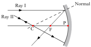
For ray I, angle of incidence = 0. So, angle of refraction is also zero. It goes straight without any deviation along path A.
For ray II, angle of incidence ө is close to 90°. It is refracted at angle r and emerges along path B, parallel to path II.
+
C.
can be both real and virtualC.
virtual and diminishedD.
between F and pole of the mirror.B.
increases in size and moves towards poleD.
all reflecting surfacesA.
virtual and diminishedA.
always virtual and diminishedD.
is thicker in the middle than at the edgesD.
between F and the optical centre of the lens.D.
- 66.6 cm.D.
Between the pole of the mirror and its principal focus.plane
concave
convex
either plane or convex
D.
either plane or convex

(a) Concave mirrors are used as reflectors in headlights of cars. The bulb is located at the focus of the concave mirror and so, the light rays after reflection from the mirror travel over a large distance as a parallel beam of high intensity.
(b) A convex mirror is used as a side/rear-view mirror of a vehicle because of the following reasons:
(i) A convex mirror always forms an erect, virtual and diminished image of an object placed anywhere in front of it.
(ii) A convex mirror has a wider field of view than a plane mirror of the same size and haence, covers a wider field of area.
(c) Large concave mirrors are used to concentrate sunlight to produce heat in solar furnaces. Concave mirrors are converging mirrors.
One-half of a convex lens is covered with a black paper. Will this lens produce a complete image of the object? Verify your answer experimentally. Explain your observations.
When the lower half of the convex lens is covered with a black paper, the complete image of the object is still formed with the uncovered lens. But, as a result of the lens being covered, the intensity of the image formed is reduced. 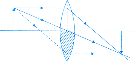
The lens considered in the question is converging lens which is the convex lens.
Given,
Object size, h = 5 cm
Object distance, u = -25 cm
Focal length, f = 10 cm
As the distances given in the question are large, so we choose a new scale where, 1 cm represents 5 cm.
So, as per the new scale,
Size of the object, h = 1 cm
Object distance, u = -5 cm
Focal length, f = 2 cm.
The ray diagram can be drawn as follows:
(i) Draw a horizontal line representing the principal axis of the convex lens.
(iii) Mark two foci F and F' on two sides of the lens, each at a distance of 2 cm from the lens.
(iv) Draw an arrow AB of height 1 cm on the left side of lens at a distance of 5 cm from the lens.
(v) Draw a line AD, parallel to principal axis and then make it pass straight through the focus (F') on the right side of the lens.
(vi) Draw a line from A passing through the centre of curvature, which goes straight without deviation.
(vii) Let the two lines starting from A meet at A' on the right side of the lens.
(viii) Draw A'B', perpendicular to the principal axis.
(ix) Now A'B', represents the real, but inverted image of the object AB.
Using the lens formula,
Also, we know that,
Since the image distance is positive, the image is real (formed on the right side of lens) at a distance of 3.3 cm. 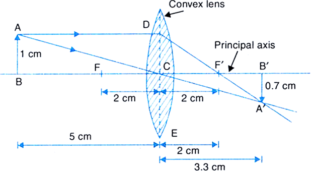
Therefore as per the original scale,
(a) Position of image A'B' = 3.3 cm × 5 = 16.5 cm from the lens on opposite side.
(b) Nature of image A’B’: Real and inverted.
(c) Height of image A'B': 0.7 × 5 = 3.5 cm, i.e., image is smaller than the object.
A concave lens of focal length 15 cm forms an image 10 cm from the lens. How far is the object placed from the lens? Draw the ray diagram.
Ray diagram:
Inorder to make the diagram, lets use a scale where 5cm = 1cm.
So, as per the new scale,
Focal length, f = -3 cm
Image distance, v = -2 cm
Steps to draw the ray diagram is mentioned below as follows:
(i) Draw a horizontal line which is called the principal axis.
(ii) Now, draw a convex lens keeping principal centre (C) on the principal axis.
(iii) Mark points F (focal length) and B (image distane) on the left side of lens at a distance of 3 cm and 2 cm respectively.
(iv) Draw a dotted line passing through F to any point on the top of the lens, say D.
(v) So, we can draw a line AD parallel to principal axis because any ray of light passing through the focal length of the lens after refraction, passes parallel to the principal axis.
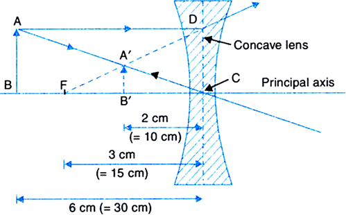
(vi) Draw a line A'B', perpendicular to principal axis from B' representing the height of the image.
(vii) Draw a line CA' backwards, so that it meets the line from D at A.
(viii) Now, draw a line AB, perpendicular to the principal axis at B from point A in the downward direction.
(ix) AB is the position of object. On measuring distance BC, it will be found to be equal to 6 cm.
Thus, the object is placed at a distance of 6 cm × 5 = 30 cm from the lens (as per the original scale).
A concave lens of focal length 15 cm forms an image 10 cm from the lens. How far is the object placed from the lens? Draw the ray diagram.
Given, a concave lens.
Focal length, f = - 15 cm
Image distance, v = - 10 cm [Concave lens forms virtual image on same side as the object, so v is - ve]
Using the lens formula,
Therefore,
Object is placed at a distance of 30 cm ( negative) from the lens.
The ray diagram is as shown below: 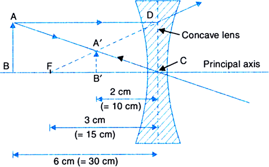
AB is the position of the object.
We are given a convex mirror.
Here,
Object distance, u = -10 cm
Focal length, f = + 15 cm [f is +ve for a convex mirror]
Image distance, v = ?
Using the mirror formula,
we have,
Thus, image distance, v = + 6 cm.
As image distance is +ve, so a virtual, erect image is formed at a distance 6 cm behind the mirror.
The magnification produced by a plane mirror is +1. What does this mean?
Magnification is the ratio of the size of the image (h') to the size of the object(h).
As,
Magnification,
For a plane mirror, m = + 1 (given).
So,
h' = h and v = -u
Magnification is equal to one indicates that the size of image is same as that of object.
Positive sign of m indicates that a virtual image is formed behind the mirror.
We are given a convex mirror.
Here, we have
Object size, h = + 5 cm
Object distance, u = -20 cm
Radius of curvature, R = + 3.0 cm [R is +ve for a convex mirror]
Focal length ,
From mirror formula,
we have,
Image distance,
Magnification,
Therefore,
A virtual and erect image of height 2.2 cm is formed behind the mirror (because v is positive) at a distance of 8.6 cm from the mirror.
Given,
Power of the lens, P = -2.0 D
Therefore,
Focal length,
Since, focal length is negative, the lens is concave.
Given,
Power of the lens, P = + 1.5 D
Therefore,
Focal length of the lens,
As the focal length is positive, the prescribed lens is converging.
We are given a concave mirror.
Here,
Object size, h = + 7.0 cm
Object distance, u = - 27 cm
Focal length, f = - 18 cm
Image distance, v = ?
Image size, h' = ?
Now, using the mirror formula,
i.e.,
The screen should be placed at a distance of 54 cm on the object side of the mirror to obtain a sharp image.
Magnification,
Image size,
The image is real, inverted and enlarged in size.

The refraction of light through spherical lenses follows new cartesian sign convention:
According to this sign convention:
(i) All distances are measured from the optical centre of the lens.
(ii) The distances measured in the same direction as the incident light are taken positive.
(iii) The distances measured in the direction opposite to the direction of incident light are taken negative.
(iv) Heights measured upwards and perpendicular to the principal axis are taken positive.
(v) Heights measured downwards and perpendicular to the principal axis are taken negative.
Assumptions used in the derivation of lens formula:
(i) The lens used is thin.
(ii) The aperture of the lens is small.
(iii) The incident and refracted rays make small angles with the principal axis.
(iv) The object is a small object placed on the principal axis.
Derivation of lens formula for a convex lens.
As shown in Fig, consider an object AB placed perpendicular to the principal axis of a thin convex lens between its F1 and 2F1.
A real, inverted and magnified image AB' is formed beyond 2F2 on the other side of the lens.
Fig. Real image formed by a convex lens.
...(1)
Also, are similar,
But MO = AB,
...(2)
From (1) and (2), we get
Using new Cartesian sign convention, we get
Object distance, BO = -u
Image distance, OB' = +v
Focal length, OF2 = + f
Dividing both sides by uvf, we get
This proves the lens formula for a convex lens.
List four characteristics of the images formed by plane mirrors.
Characteristics of the images formed by plane mirrors are:
i) The image formed is of the same size as that of the object.
ii) Images are formed behind the mirrors and are at the same distance from the mirror as that of the object.
iii) The virtual and erect image is formed.
iv) The images are laterally inverted.
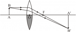
To construct a ray diagram we use two rays of light which are so chosen that it is easy to determine their directions after reflection from the mirror. Choose these two rays and state the path of these rays after reflection from a concave mirror. Use these two rays to find the nature and position of the image of an object placed at a distance of 15 cm from a concave mirror of focal length 10 cm.
The two rays chosen for the construction of ray diagram is:
Ray 1: When the incident ray is parallel to the principal axis, the reflected ray will pass through the focus of concave mirror or it appears to pass through the focus of convex mirror.
Ray 2: When the incident ray passes through or appears to pass through the centre of curvature, the light, after reflection from the spherical mirror, reflects back along the same path.
The image formed is real, inverted, magnified and is formed beyond the centre of curvature.
(a) State the laws of refraction of light. Explain the term absolute refractive index of a medium and write an expression to relate it with the speed of light in vacuum.
(b) The absolute refractive indices of two media 'A' and 'B' are 2.0 and 1.5 respectively. If the speed of light in medium 'B' is , calculate the speed of light in:
(i) vacuum,
(ii) medium 'A'.
Laws of refraction states that:
(1) The incident ray, the refracted ray and the normal to the interface of two media at the point of incidence all lie in the same plane.
(2) For the light of a given color and for given pair of media, the ratio of the sine of the angle of incidence to the sine of the angle of refraction is constant.
This is also known as Snell's Law.
Mathematically it can be written as:
Here,  is the refractive index of medium B with respect to medium A.
Refractive index of a medium with respect to the vacuum is known as the absolute refractive index.
 c is the speed of light in vacuum and c is the speed of light in medium B.
b) Absolute refractive of medium A,  =2
=2
Absolute refractive index of medium B,  =1.5
=1.5
"A convex lens can form a magnified erect as well as a magnified inverted image of an object placed in from of it." Draw ray diagram to justify this statement stating the position of the object with respect to the lens in each case.
An object of height 4 cm is placed at a distance of 20 cm from a concave lens of focal length 10 cm. Use lens formula to determine the position of the image formed.
a) When the object is placed between O and F1, magnified erect image is formed. 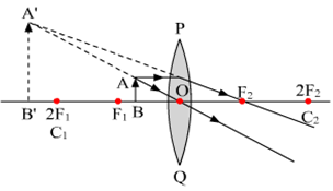
b) When the object is placed between F1 and 2F1 , magnified inverted image is formed.
Object distance, u = 20 cm
Image distance, v=?
Focal length, f = 10 cm
According to the sign convention, f = -10 cm and u=-20 cm
Now, using the lens formula,
The image is formed at a distance of 6.6 cm from the lens at the same side where the object is placed.
Study the following diagram and select the correct statement about the device ‘X’:
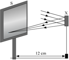
Device 'X' is a concave mirror of radius of curvature 12 cm
Device 'X' is a concave mirror of focal length 6 cm
Device 'X' is a concave mirror of focal length 12 cm
Device 'X' is a convex of mirror of focal length 12 cm
C.
Device 'X' is a concave mirror of focal length 12 cm
Correct option is C.
From the figure, we can see that the light rays coming from infinity get reflected by the device 'X' and converge at a point at a distance 12 cm from it. Therefore, the device 'X' is a concave mirror of focal length 12 cm.
A student has obtained a point image of a distant object using the given convex lens. To find the focal length of the lens he should measure the distance between the :
lens and the object only
lens and the screen only
Object and the image only
lens and the object and also between the object and the image
B.
lens and the screen only
The correct option is B.
Here, using a convex lens the student has obtained a point image of a distant object.
The lens formula is,
 ; v s the image distance,
u is the object distance and
f is the focal length of the lens.
We have a distant object so u = .
Thus,  .
.
So, to find the focal length of the lens, image distance should be known, which is the distance between the lens and the screen.
For students P, Q, R and S traced the path of a ray of light passing through a glass slab for an angle of incidence 40° and measured the angle of refraction. The values as measured by them were 18°; 22°; 25° and 30° respectively. The student who has performed the experiment methodically is
P
Q
R
S
C.
R
The correct option is C.
Given, angle of incidence = 40o
The angle of refraction (r = 25o) measured by student R is most appropriate as per Snell’s law.
According to Snell’s law, we have
 and refractive index of glass is 1.5.
After tracing the path of a ray of light through a glass prism a student marked the angle of incidence ( i), angle of refraction ( r) angle of emergence ( e) and the angle of deviation ( D) as shown in the diagram. The correctly marked angles are:
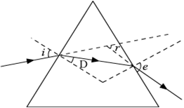
i and r
i and e
i, e and D
B.
i and e
Correct option is B.
Angle of incidence and angle of emergence have been correctly marked.
To find the image-distance for varying object-distances in case of a convex lens, a student obtains on a screen a sharp image of a bright object placed very far from the lens. After that he gradually moves the object towards the lens and each time focuses its image of the screen.
(a) In which direction – towards or away from the lens, does he move the screen to focus the object?
(b) What happens to the size of image – does it increase or decrease?
(c) What happen when he moves the object very close to the lens?
a) The position of the object moves away from the lens, as the student moves the object towards the lens. The screen should be moved away from the lens in order to obtain a sharp image.
b) When the object is moved near the lens, size of the image increases.
c) When the object is moved very close to the lens, it can be assumed to be placed between the focus and the optical centre. Then, the image formed is virtual, erect and enlarged.
Draw a ray diagram to show the path of the reflected ray corresponding to an incident ray which is directed parallel to the principal axis of a convex mirror. Mark on it the angle of incident and the angle of reflection.
The figure drawn below illustrates the path of reflected ray corresponding to an incident ray which is directed parallel to the principal axis of a convex mirror. 
A spherical mirror produces an image of magnification −1 on a screen placed at a distance of 50 cm from the mirror.
(a) Write the type of mirror.
(b) Find the distance of the image from the object.
(c) What is the focal length of the mirror?
(d) Draw the ray diagram to show the image formation in this case.
a) The image formed is real because magnification is negative. Therefore, the type of mirror used is a concave mirror.
b) 
So, distance of the image from the object = |u| +|v| =100 cm
c) Using the mirror formula, we have
d) The given diagram shows the image formation.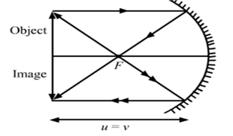
State the laws of refraction of light. If the speed of light in vacuum is 3 × 10⁸ ms−1, find the speed of light in a medium of absolute refractive index 1.5.
The laws of refraction states that,

n12is the relative refractive index of medium 1 with respect to medium 2.
2. Second law: The incident ray, refracted ray and the normal to the interface of the two media at the point of incidence, all the three lie in the same plane.
When light ray is propagating from medium 1 to medium 2, then the refractive index of medium 1 with respect to medium 2 is expressed as,
 ; is the speed of light in medium 1 and 2.
Numerical:
Given, refractive index of the medium = 1.5
So, 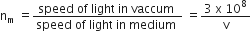
 is the required speed of light in medium.
A student wants to project the image of a candle flame on the walls of school laboratory by using a lens:
(a) Which type of lens should be use and why?
(b) At what distance in terms of focal length 'F' of the lens should be place the candle flame so as to get (i) a magnified, and (ii) a diminished image respectively on the wall? Draw ray diagram to show the formation of the image in each case?
a) A convex lens should be used to form a real image.
b) i) In order to get a magnified image, the candle flame should be placed between F and 2F.
ii) The diminished image is obtained when the object is kept at a distance greater than 2F.
c) Ray diagram for the formation of magnified image is,
Ray diagram for the formation of the diminished image is:
A student has obtained the image of a distant object with a concave mirror to determine its focal length. If he has selected a well-illuminated red building as an object, which of the following correctly describes the features of the image formed?
Virtual, inverted and diminished image in red shade
Real, erect and diminished image in pink shade
Real, inverted and diminished image in red shade
Virtual, erect and enlarged image in red shade.
C.
Real, inverted and diminished image in red shade
The correct option is C.
The object should be taken at infinity in order to measure the focal length of the mirror. Therefore, the image formed by the concave mirror would be real, inverted, diminished and red in shade.
A student has obtained an image of a distant object on a screen to determine the focal length F1 of the given lens. His teacher, after checking the image, gave him another lens of focal length F2 and asked him to focus the same object on the same screen. The student found that to obtain a sharp image, he has to move the lens away from the screen. From this finding, we may conclude that both the lens given to the students were:
Concave and F1 < F2
Convex and F1< F2
Convex and F1> F2
Concave and F1> F2
C.
Convex and F1> F2
Here, the correct option is C.
Since the image formed is real, the lens used is convex. Given that, the image distance is increasing therefore, the object distance is decreasing. 
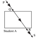
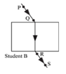
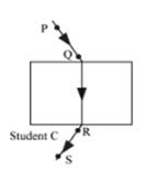
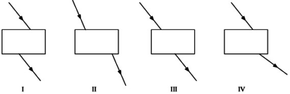
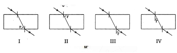
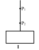
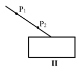
Study the following four experimental set-ups I, II, III and IV for the experiment, "To trace the path of a ray of light through a rectangular glass slab."
Which of the marked set-ups is likely to give best results( P1 and P2 are the position of pins fixed on the incident ray)?
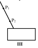
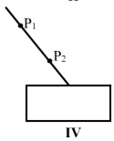
B.
The correct option is B.
Experiment II will give the best result because it has the largest angle of incidence, due to which the lateral displacement between the incident ray and emergent ray will be maximum.
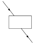
On the basis of the experiment, 'To trace the path of a ray of light through a rectangular glass slab', students of a class arrived at which one of the following conclusions?
Angle of incidence is greater than the angle of emergence.
Angle of emergence is smaller than the angle of refraction.
Emergent ray is parallel to the refracted ray
Incident ray and emergent ray are parallel to each other.
D.
Incident ray and emergent ray are parallel to each other.
The correct option is D.
The correct conclusion is Incident ray and emergent ray are parallel to each other.
A student was asked by his teacher to find the image distance for various object distances in case of a given convex lens. He performed the experiment with all precautions and noted down his observations in the following table:
|
S.No |
Object distance (cm) |
Image distance (cm) |
|
1 |
60 |
15 |
|
2 |
48 |
16 |
|
3 |
36 |
21 |
|
4 |
24 |
24 |
|
5 |
18 |
36 |
|
6 |
16 |
48 |
After checking the observation table the teacher pointed out that there is a mistake in recording the image distance in one of the observations. Find the serial number of observations having faulty image distance.
2
3
5
6
B.
3
The correct option is B.
In observation No. 3 the focal length comes out to be 13.26 cm whereas, the focal length for all other observation is 12 cm.
A student has obtained a magnified image of a flame on a screen using a convex lens. To draw the corresponding ray diagram to show the image formation, which of the following two rays whose paths after refraction are shown, should he select?
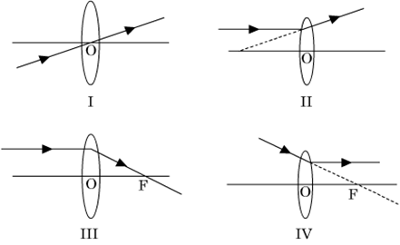
I and II
II and III
III and IV
I and III
D.
I and III
The correct option is D.
Convex lens is a converging lens. Therefore, rays I and III represent the path of the refracting ray from a convex lens (converging lens). Figure II and IV show the refracting ray being diverged. So, the ray diagrams are incorrect.
State the two laws of reflection of light.
Laws of reflection states that:
i. The angle of incidence is equal to the angle of reflection.
ii. The incident ray, the reflected ray and the normal to the mirror, all lie in the same plane.
Draw the ray diagram and also state the position, the relative size and the nature of image formed by a concave mirror when the object is placed at the centre of curvature of the mirror.
The ray diagram when object is placed at the centre of curvature is given below: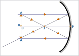
Position of the image: at the centre of curvature
Size of the image: Enlarged
Nature of the image: Real and inverted(i) “The refractive index of diamond is 2.42”. What is the meaning of this statement?
(ii) Name a liquid whose mass density is less than that of water but it is optically denser than water.
(i) “The refractive index of diamond is 2.42” implies that the ratio of the sine of the angle of incidence to the sine of the angle of refraction is equal to 2.42.
(ii) Kerosene has a refractive index of 1.44. Kerosene is optically denser than water, although its mass density is less than water.
(a) If the image formed by a lens is diminished in size and erect, for all positions of the object, what type of lens is it?
(b) Name the point on the lens through which a ray of light passes undeviated.
(c) An object is placed perpendicular to the principal axis of a convex lens of focal length 20 cm. The distance of the object from the lens is 30 cm. Find (i) the position (ii) the magnification and (iii) the nature of the image formed.
(a) If the image formed by a lens is diminished in size and erect, for all positions of the object, then the lens is a concave lens.
(b) The point on the lens through which a ray of light passes undeviating is known as Pole.
(c) Given,
Object distance, u = -30 cm
Focal length, f =20 cm
i) Now, using the len’s formula,
(iii) Image formed is inverted.
One-half of a convex lens is covered with a black paper. Will such a lens produce an image of the complete object? Support your answer with a ray diagram.
(b) An object 5 cm high is held 25 cm away from a converging lens of focal length 10 cm.
(i) Draw the ray diagram and
(ii) Calculate the position and size of the image formed.
(iii) What is the nature of the image?
(a) Image is formed by a large number of rays from the object. If one part of the lens is blackened, image will be formed. But, intensity of the image will be reduced.
(b) i)

Object distance, u = -25 cm
Focal length, f = 10 cm
Height of the image, h = 5 cm
ii) Now, using the lens formula,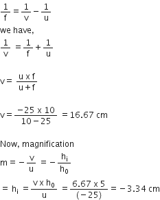
(iii) Negative sign indicates that the image is real & inverted.
Rahim recorded the following sets of observations while tracing the path of a ray of light passing through a rectangular glass slab for different angles of incidence.
|
S. No. |
Angle of incidence |
Angle of refraction |
Angle of emergence |
|
The correct observations are recorded at a serial number:
|
I |
45o |
41o |
45o |
|
|
II |
40o |
38o |
38o |
|
|
III |
45o |
41o |
40o |
|
|
IV |
41o |
45o |
41o |
|
A.
|
I |
45o |
41o |
45o |
|
Mohan obtained a sharp inverted image of a distant tree on the screen placed behind the lens. He then moved the screen and tried to look through the lens in the direction of the object. He would see:
a blurred image on the wall of the laboratory.
an erect image of the tree on the lens.
no image as the screen has been removed
an inverted image of the tree at the focus of the lens.
A.
a blurred image on the wall of the laboratory.
“A ray of light incident on a rectangular glass slab immersed in any medium emerges parallel to itself.” Draw labelled ray diagram to justify the statement.
The figure below illustrates the phenomenon refraction of a ray of light passing through a glass prism.
EF is the incident ray and GH is the emergent ray which is parallel to the incident ray.
Mention the types of mirrors used as (i) rear view mirrors, (ii) shaving mirrors. List two reasons to justify your answers in each case.
(i) Convex mirrors are used as Rear view mirrors because:
(ii) Concave mirrors are used as shaving mirrors because:
An object of height 6 cm is placed perpendicular to the principal axis of a concave lens of focal length 5 cm. Use lens formula to determine the position, size and nature of the image if the distance of the object from the lens is 10 cm.
Given,
Height of object, h1 = 6 cm,
Focal length of lens, f = -5 cm, and
Object distance, u = -10 cm
Now, using the lens formula, 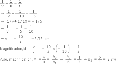
Thus, the image of size 2 cm will be formed in front of the lens at a distance of 3.33 cm from the lens. The nature of the image is virtual and erect.
(a) State the laws of refraction of light. Give an expression to relate the absolute refractive index of a medium with speed of light in vacuum.
(b) The refractive indices of water and glass with respect to air are 4/3 and 3/2 respectively. If the speed of light in glass is 2 × 10⁸ ms−1, find the speed of light in (i) air, (ii) water.(a) Laws of refraction states that:
First law of refraction: The ratio of the sine of the angle of incidence to the sine of the angle of refraction is constant. This is known as Snell’s law.
Mathematically, we have 
Here, nab is the relative refractive index of medium a with respect to medium b.
Second law of refraction: The incident ray, the refracted ray, and the normal to the interface of two media at the point of incidence; all lie in the same plane.
If the light ray goes from medium 1 to 2 then the refractive index of medium 1 with respect to medium 2 is,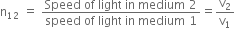
where v1 and v2 are the speeds of light in medium 1 and 2 respectively.
Given,
Refractive index of water, nw = 4/3, and
Refractive index of glass, ng= 3/2
Speed of light in glass, vg = 2×10⁸ m/s
i.  where, na is the refractive index of light in air and va is the speed of light in air.
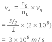
is the required speed of light in air.
ii. Speed of light in water is given by,
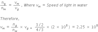
A student focused the image of a distant object using a device ‘X’ on a white screen ‘S’ as shown in the figure. If the distance of the screen from the device is 40 cm, select the correct statement about the device.
The device X is a convex lens of focal length 20 cm.
The device X is a concave mirror of focal length 40 cm.
The device X is a convex mirror of radius of curvature 40 cm.
The device X is a convex lens of focal length 40 cm.
D.
The device X is a convex lens of focal length 40 cm.
A student obtained a sharp image of a burning candle, placed at the farther end of a laboratory table, on a screen using a concave mirror. For getting better value of focal length of the mirror, the subject teacher suggested him for focusing a well illuminated distant object. What should the student do?
He should move the mirror away from the screen.
He should move the mirror slightly towards the screen.
He should move the mirror as well as the screen towards the newly selected object.
He should move only the screen towards the newly selected object.
B.
He should move the mirror slightly towards the screen.
On increasing the image distance, the object distance decreases. So, the mirror-screen distance should be decreased. That is, the mirror should be moved towards the screen.
After tracing the path of rays of light through a glass slab for three different angles of incidence, a student measured the corresponding values angle of refraction r and angle of emergence e and recorded them in the table given below:
|
S. No. |
∠i |
∠r |
∠e |
|
I |
30° |
20o |
31o |
|
II |
40o |
25o |
40o |
|
III |
50o |
31o |
49o |
A)
B)
C) I and III
D) I, II and III
I and II
II and III
I and III
I, II and III
D.
I, II and III
For light rays passing through a glass slab, the following conditions should hold true:

The given observations satisfy both these conditions.
Select from the following the best set-up for tracing the path of a ray of light through a rectangular glass slabs:
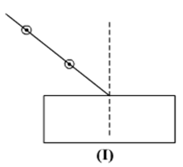
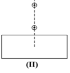
A.
The incoming light should not fall perpendicularly as the light will emerge straight and refraction cannot be traced. The light rays should not be very close or far from the normal as the emergent rays are difficult to trace.
In an experiment to trace the path of a ray of light through a glass prism for different values of angle of incidence a student would find that the emergent ray:
is parallel to the incident ray
Perpendicular to the incident ray
is parallel to the refracted ray
bends at an angle to the direction of incident ray
D.
bends at an angle to the direction of incident ray
The light ray gets refracted two times at different angles. So, emergent ray bends at an angle towards the direction of incident ray.
Study the following ray diagrams:
i
. 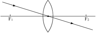
ii.
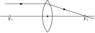
iii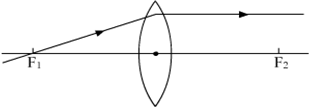
iv. 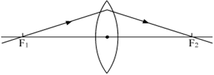
The diagrams showing the correct path of the ray after passing through the lens are:
II and III only
I and II only
I, II and III
I, II and IV
C.
I, II and III
The light rays passing through the optical centre of lens traces the same path after refraction.
The light rays coming from a distant object passing parallel to principal axis, after refraction passes through the second focus of the lens.
The light rays passing through the first focus become parallel to the principal axis after passing through the lens.
Out of the five incident rays shown in the figure find the three rays that are obeying the laws of refraction and may be used for locating the position of image formed by a convex lens:
1, 2 and 3
2, 3 and 4
3, 4 and 5
1, 2 and 4
B.
2, 3 and 4
Rays (2), (3) and (4) obey the laws of refraction.
While performing the experiment to trace the path of a ray of light passing through a glass prism, four students marked the incident ray and the emergent ray in their diagrams in the manner shown below.
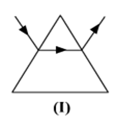
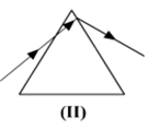
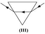
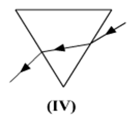
C.
When light goes from rarer medium to denser medium it bends towards the normal. The light bends away from the normal when it goes from a denser medium to rarer medium.
This condition is fulfilled in figure (III).
When we place a glass prism in the path of a narrow beam of white light a spectrum is obtained. What happens when a second identical prism is placed in an inverted position with respect to the first prism? Draw a labelled ray diagram to illustrate it.
The sunlight or white light is dispersed into its seven constituent colors and a spectrum is formed on passing through the first prism. The other inverted prism recombines all the seven colors and gives a white light. 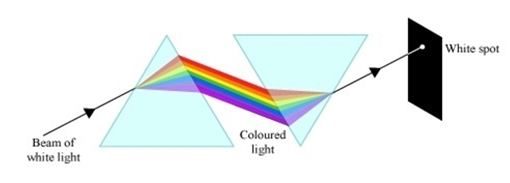
List four properties of the image formed by a convex mirror.
The image formed by a convex mirror is:
(i) always erect
(ii) smaller in size as compared to the object.
(iii) Virtual
(iv) Image is always formed between focus and pole and is behind the mirror.
A student traces the path of a ray of white light through a rectangular glass slab and marks, the angles of incidence (∠i) , refraction (∠r) and emergence (∠e) as shown. Which angle or angles has he not marked correctly?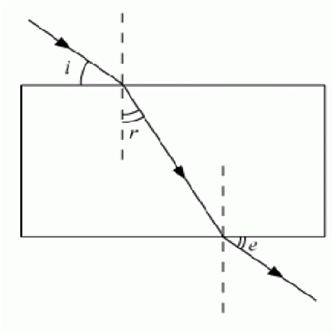
∠i only
∠i and ∠r
∠i and ∠e
∠r and ∠e
C.
∠i and ∠e
Incident and emergent angles are always measured from the normal of the plane.
While tracing the path of a ray of light passing through a rectangular glass slab a student tabulated his observations as given below:
|
S.NO. |
∠i |
∠r |
∠e |
|
I |
60° |
40° |
61° |
|
II |
50o |
36o |
51o |
|
III |
40o |
28o |
39o |
|
IV |
30o |
20o |
31o |
D.
|
IV |
30o |
20o |
31o |
The correct option is D.
As per Snell’s law
The ratio of the sine values of i and r should be 1.5.
Note: Refractive index of glass = 1.5 and refractive index of air is 1.
To determine focal length of a concave mirror a student obtains the image of a well-lit distant object on a screen. To determine the focal length of the given concave mirror he needs to measure the distance between:
mirror and the object
mirror and the screen
screen and the object
screen and the object and also mirror and the screen
B.
mirror and the screen
Focal length is the distance between the focus and the mirror. The image of the distant object forms at the focus of the mirror.
A student obtained a sharp image of the grills of a window on a screen using a concave mirror. His teacher remarked that for getting better results a well-lit distant object (preferably the sun) should be focused on the screen. What should be done for this purpose?
Move the screen slightly away from the mirror
Move the mirror slightly towards the screen
Move the screen and the mirror away from the object
Move the screen and the mirror towards the object
B.
Move the mirror slightly towards the screen
When the image distance increases, object distance decreases. Thus, distance between the mirror and screen will decrease. So, the mirror should be moved towards the screen.
To determine the focal length of a convex lens by obtaining a sharp image of a distant object we generally follow the following steps which are not in proper sequence.
(a) Hold the lens between the object and the screen
(b) Measure the distance between the lens and the screen
(c) Select a well-lit distant object
(d) Place a screen opposite to the object on the lab table
(e) Adjust the position of the lens to form a sharp image
The correct sequence of these steps is:
c, a, d, e, b
c, d, a, e, b
c, d, e, a, b
c, a, e, d, b
B.
c, d, a, e, b
The right sequence of steps is c,d,a,e,b.
The image of a candle flame placed at a distance 30 cm from a spherical lens is formed on a screen placed at a distance of 60 cm from the lens. Identify the type of lens and calculate its focal length. If the height of the flame is 2.4 cm, find the height of its image.
Given,
Object distance, u = − 30 cm
Image distance, v = 60 cm
Height of the object, h = 2.4 cm
Using lens formula,

State the type of mirror preferred as
(i) Rear view mirror in vehicles, (ii) shaving mirror.
Justify your answer giving two reasons in each case.
i) Convex mirrors are used as rear-view mirrors in vehicles because they form a virtual, erect, and diminished image of the objects placed in front of them. Moreover, they give a wider field of view enabling the driver to see the traffic behind them.
ii) Concave mirrors are used for shaving as it gives a magnified and erect image of the face.
List the sign conventions for reflection of light by spherical mirrors. Draw a diagram and apply these conventions in the determination of focal length of a spherical mirror which forms a three times magnified real image of an object placed 16 cm in front of it.
: Sign conventions for spherical mirrors
I. Objects are always placed to the left of the mirror i.e. light must fall on the mirror from left to right.
II. All distances are measured from the pole of the mirror.
III. Distances along the direction of the incident ray (along positive X - axis) are taken as positive, while distances along the direction of the reflected ray (along negative X-axis) are taken as negative.
IV. Heights measured perpendicular to and above the principal axis (along positive Y-axis) are taken as positive.
V. Heights measured perpendicular to and below the principal axis (along negative Y-axis) are taken as negative.

Given,
Magnification, m = −3 (real image is inverted always)
Object distance, u = −16 cm
Now,
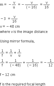
State the law of refraction of light that defines the refractive index of a medium with respect to the other. Express it mathematically. How is refractive index of any medium 'A' with respect to a medium 'B' related to the speed of propagation of light in two media A and B? State the name of this constant when one medium is vacuum or air.
The refractive indices of glass and water with respect to vacuum are 3/2 and 4/3 respectively. If the speed of light in glass is 2 × m/s, find the speed of light in (i) vacuum, (ii) water.
First law of refraction also known as Snell’s law defines the refractive index of a medium with respect to the other medium.
First law of refraction states that, the ratio of the sine of the angle of incidence to the sine of the angle of refraction is constant. This is known as Snell’s law.
Mathematically, it can be given as follows:
Here,  is the relative refractive index of medium b with respect to medium a.
Consider a ray of light travelling from medium B into medium A. Let v1 be the speed of light in medium A and v2 be the speed of light in medium B. Then,
Refractive index of medium A with respect to medium B is given by

If one medium is vacuum or air then the constant is known as absolute refractive index of the medium.
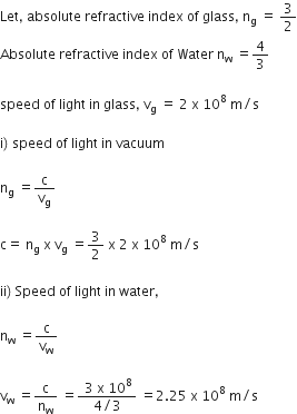
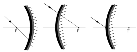
The path of the ray of light after reflection is as shown below: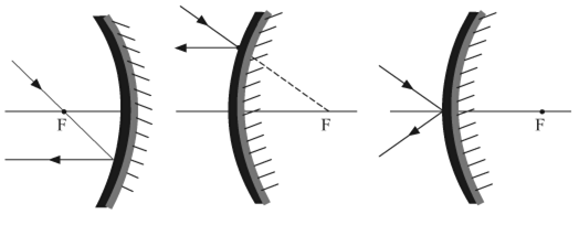
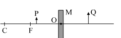
a)
i) Pole: A pole is the central point of the reflecting surface of a spherical mirror. Pole lies on the mirror and is denoted by P.
ii) Centre of curvature: The centre of a sphere from which the given spherical mirror (convex or concave) is obtained is called as centre of curvature.
It is denoted by the letter C.
iii) Principal axis: An imaginary straight line passing through the pole and centre of curvature is termed as the principal axis.
iv) Principal focus: The focus (F) is the point on the principal axis of a spherical mirror where all the incident rays parallel to the principal axis meet or appear to diverge from after reflection.
b)
Concave mirror: The focus lies on the same side of the reflecting surface.
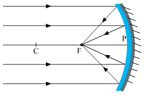

a)
When an object is placed in front of the lens between its optical centre and principal focus, the image is formed beyond 2F1 (on the same side of the object), and the ray diagram is obtained is as follows:
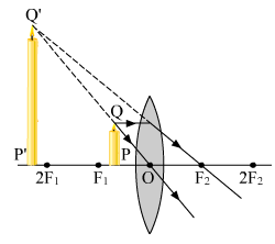 b)
b) 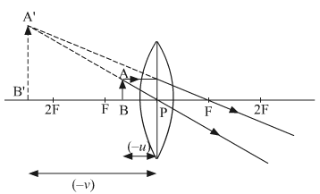


C.
screen towards the mirrorThe object, i.e., the distant building is at a distance of 1 km from the laboratory. That is, for the concave mirror, the building (object) is at infinity. In order to obtain a sharp image of the building, the student must slightly move the screen towards the mirror.
C.
inverted and diminishedThe image formed by the object will be inverted and diminished.
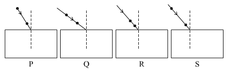
P
Q
R
S
D.
S
Among the given options, s will be the most suitable setup for tracing a ray of light passing through a rectangular glass slab.
i) In which direction, towards the screen or away from the screen, does he move the lens?
ii) What happens to the size of the image? Does it decrease or increase?
iii) What happens to the image on the screen when he moves the object very close to the lens?
Name the type of mirrors used in the design of solar furnaces. Explain how high temperature is achieved by this device.
Concave mirrors are used for the design of solar furnaces because they are converging mirrors. When a solar furnace is placed at the focus of a large concave mirror, it focuses a parallel beam of light on the furnace. Thus, a high temperature is achieved after a few minutes.
The object will be placed at centre of curvature.
If the object is moved 20 cm towards the mirror, then image will be formed at infinity. Here, focal length of the mirror is 20 cm. And the new position of the object would be at the focus of the mirror.
The ray diagram for the formation of the image is as shown below: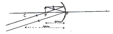
It is desired to obtain an erect image of an object, using concave mirror of focal length of 12 cm
(i) What should be the range of distance of an object placed in front of the mirror?
(ii) Will the image be smaller or larger than the object. Draw ray diagram to show the formation of image in this case.
(iii) Where will the image of this object be, if it is placed 24 cm in front of the mirror ? Draw ray diagram for this situation also to justify your answer.
Show the positions of pole, principal focus and the centre of curvature in the above ray diagrams.
i) Range of object distance will be between 0 cm and 12 cm because the focal length is given as 12 cm.
ii)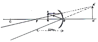
That is, the image formed is larger than the object.
iii)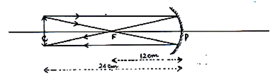
Image will be formed at a distance of 24 cm in front of the mirror.
In the above ray diagram, pole is given by P, principal focus is given by F and centre of curvature is C.
(a) Define optical centre of a spherical lens.
(b) A divergent lens has a focal length of 20 cm. At what distance should an object of height 4 cm from the optical centre of the lens be placed so that its image is formed 10 cm away from the lens. Find the size of the image also.
(c) Draw a ray diagram to show the formation of image in above situation.
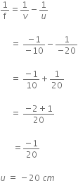


In your laboratory you trace the path of light rays through a glass slab for different values of angle of incidence (i) and in each case measure the values of the corresponding angle of refraction (r) and angle of emergence (e). On the basis of your observations your correct conclusion is:
 i is more than
  r, but nearly equal to
  e
e
 i is less than
  r, but nearly equal to
  e
e
 i is more than
  e, but nearly equal to
  r
r
 i is less than
  e, but nearly equal to
  r
r
A.
i is more than r, but nearly equal to e
An object of height 2.5 cm is placed at a distance of 15 cm from the optical centre ‘O’ of a convex lens of focal length 10 cm. Draw a ray diagram to find the position and size of the image formed. Mark optical centre ‘O’, principal focus F and height of the image on the diagram.
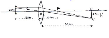
The absolute refractive indices of glass and water are 4/3 and 3/2, respectively. If the speed of light in glass is 2 × 10⁸m/s, calculate the speed of light in,
a) vacuum
b) water
Refractive index of glass,  = 3/2
= 3/2
Therefore,
That is,
Speed of light in vacuum,
c = 
Refractive index of water, 


Speed of light in water = 2.25 x 10⁸ m/s
Note: In the question given, the refractive indices of glass and water is wrong. The refractive index of glass and water is interchanged.
The image formed by a convex mirror is always erect and diminished. Therefore, the given mirror is a convex mirror.
Let, the object be placed between the pole (P) and infinity in front of a convex mirror.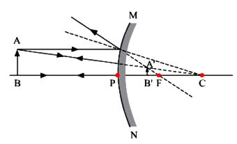
Convex mirrors is used as rear view mirrors in vehicles because it gives a wide field of view and the image formed is always virtual, erect and diminished image.
Thus, it enables the driver to view a much larger area of the traffic behind.
What is meant by power of a lens? Define its SI unit.
You have two lenses A and B of focal lengths +10 cm and –10 cm, respectively. State the nature and power of each lens. Which of the two lenses will form a virtual and magnified image of an object placed 8 cm from the lens? Draw a ray diagram to justify your answer.
The power of a lens is defined as the reciprocal of its focal length. It is denoted using the letter P.
Mathematically, ;
;
where f is the focal length of the lens.
Given:
Focal length of the lens A, FA = +10 cm = +0.1 m
Focal length of lens B, FB = -10 cm = -0.1 m
Power of lens A, P = 
P = +10 D
Since, power is positive, the lens is a converging lens or convex lens.
Power of lens B, 
i.e., P = 
Therefore, P = -10 D
Since, power is negative, it is a diverging lens or concave lens.
Given, that the object is placed 8 cm from the lens, which is at a distance less than 10 cm.
In a convex lens, when the object is placed between the pole and focus, image formed is always virtual and diminished.
Therefore, the lens will produce a virtual and magnified image of the object.
Ray diagram is as shown below: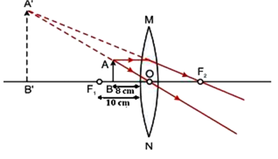
One-half of a convex lens of focal length 10 cm is covered with a black paper. Can such a lens produce an image of a complete object placed at a distance of 30 cm from the lens? Draw a ray diagram to justify your answer.
A 4 cm tall object is placed perpendicular to its principal axis of a convex lens of focal length 20 cm. The distance of the object from the lens is 15 cm. Find the nature, position and the size of the image.
The convex lens will produce the complete image of the object even though half of the lens is covered. This is because the other half of the lens can refract the light coming from the object. However, the intensity of the image will be reduced.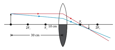
Numerical:
Given,
Height of the object, h = 4 cm
Focal length of the convex lens, f = 20 cm
Object distance, u = -15 cm
Using the lens formula,
Therefore,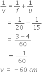
Thus, the image is formed 60 cm in front of the lens on the same side as that of the object.
Since v is negative, the image formed is virtual.
Using the formula for magnification of a lens,
That is,
h' = 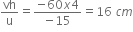
Since the height of the image is positive and greater than the height of the object, the image formed is erect and magnified.
Therefore, the image is virtual, erect and magnified.
A student obtains a sharp image of the distant window (W) of the school laboratory on the screen (S) using the given concave mirror (M) to determine its focal length. Which of the following distances should he measure to get the focal length of the mirror?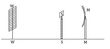
MW
MS
SW
MW-MS
B.
MS
The focal length of a concave mirror is the distance between its pole and principal focus. That is, the distance of the image formed (screen) from the concave mirror will be equal to the focal length of the concave mirror.
According to the mirror formula,
We have,
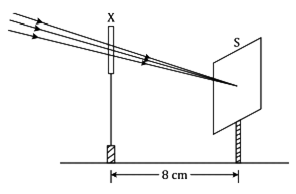
This device is a concave lens of focal length 8 cm
This device is a convex mirror of focal length 8 cm
This device is a convex lens of focal length 4 cm
This device is a convex lens of focal length 8 cm
D.
This device is a convex lens of focal length 8 cm
The incident rays after passing through the lens converge at the focus. So, the device 'X' is a converging or a convex lens. The distance between the lens and the screen gives the focal length of the lens.
A student traces the path of a ray of light through a rectangular glass slab for the different values of angle of incidence. He observes all possible precautions at each step of the experiment. At the end of the experiment, on analyzing the measurements, which of the following conclusions is he likely to draw?


A.
The incident rays after passing through the lens converge at the focus. So, the device 'X' is a converging or a convex lens. The distance between the lens and the screen gives the focal length of the lens.
A 4 cm tall object is placed on the principal axis of a convex lens. The distance of the object from the optical centre of the lens is 12 cm and its sharp image is formed at a distance of 24 cm from it on a screen on the other side of the lens. If the object is now moved a little away from the lens, in which way (towards the lens or away from the lens) will he have to move the screen to get a sharp image of the object on it again? How will the magnification of the image be affected?
Given that,
Object distance, u = −12 cm
Image distance, v = 24 cm
The focal length of the lens is 8 cm.
Now if the object is moved away from the lens, the screen has to be moved towards the lens. This is because when we move the object away from the lens, the object distance is increased. Hence, by the lens formula, the image distance decreases.
Magnification is given as,
Since, the image distance (v) decreases, the value of magnification also decreases.
A concave mirror of focal length 15 cm can form a magnified, erect as well as inverted image of an object placed in front of it.' Justify this statement stating the position of the object with respect to the pole of the mirror in both the cases for obtaining the images.
The image will be placed between pole P and focus F for magnified and erect image.
For magnified and inverted image the object is placed either at focus or in between F and C.
A student wants to project the image of a candle flame on a screen 90 cm in front of a mirror by keeping the flame at a distance of 15 cm from its pole.
(a) Suggest the type of mirror he should use.
(b) Determine the linear magnification in this case.
(c) Find the distance between the object and its image.
(d) Draw ray diagram to show the image formation in this case.
a) Concave mirror should be used inorder to project the flame of the candle.
b) Linear magnification of the concave mirror is,
c) Distance between the object and the image = 90 - 15 = 75 cm
d) The image formation is as shown below: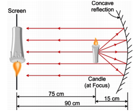
Draw a ray diagram to show the path of the refracted ray in each of the following cases:
A ray of light incident on a concave lens is:
(i) passing through its optical centre.
(ii) parallel to its principal axis.
(iii) directed towards its principal focus.
For a concave lens,
i) The ray diagram for a ray of light passing through the optical centre of the concave lens will emerge without any deviation.
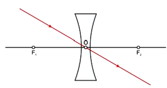

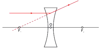
(a) Explain the following terms related to spherical lenses:
(i) optical centre
(ii) centres of curvature
(iii) principal axis
(iv) aperture
(v) principal focus
(vi) focal length
(b) A converging lens has focal length of 12 cm. Calculate at what distance the object should be placed from the lens so that it forms an image at 48 cm on the other side of the lens.
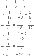
A student focused the Sun rays using an optical device 'X' on a screen S as shown.
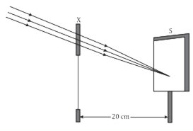
Convex lens of focal length 10 cm.
Convex lens of radius of curvature 20 cm
Convex lens of focal length 20 cm
Concave mirror of focal length 20 cm
A.
Convex lens of focal length 10 cm.
Optical device ‘X’ is a convex lens as sun rays are focused on the screen.
A student has obtained an image of a well-illuminated distant object on a screen to determine the focal length, F1 of the given spherical mirror. The teacher then gave him another mirror of focal length, F2 and asked him to obtain a focused image of the same object on the same screen. The student found that in order to focus the same object using the second mirror, he has to move the mirror away from the screen. From this observation, it may be concluded that both the spherical mirrors given to the student were (select the correct option):
Concave and F1 < F2
Concave and F1 > F2
Convex and F1 < F2
Convex and F1 > F2
A.
Concave and F1 < F2
Since the image is focused, the spherical mirror is a concave mirror. For second mirror the distance is increased to focus the image on the screen. Hence, focal length is more than that of first mirror.
A student is using a convex lens of focal length 18 cm to study the image formation by it for the various positions of the object. He observes that when he places the object at 27 cm, the location of the image is at 54 cm on the other side of the lens. Identify from the following diagram the three rays that are obeying the laws of refraction and may be used to draw the corresponding ray diagram.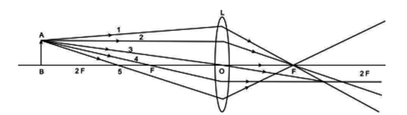
1, 2 and 4
1,3 and 5
2, 4 and 5
2, 3 and 4
D.
2, 3 and 4
Ray 2, 3 and 4 are obeys the laws of refraction.
Ray 2 is parallel to the principal axis and passes through the principal focus after refraction.
Ray 3 passes from the optical centre of the lens and emerges without any deviation.
Ray 4 is passing through the principal focus and after refraction from a convex lens emerges parallel to the principal axis.
Ray 1 and 5 cannot pass through the focus after refraction as they are not parallel to the principal axis.
A student is using a convex lens of focal length 10 cm to study the image formation by a convex lens for the various positions of the object. In one of his observations, he may observe that when the object is placed at a distance of 20 cm from the lens, its image is formed at (select the correct option)
20 cm on the other side of the lens and is of the same size, real and erect.
40 cm on the other side of the lens and is magnified, real and inverted.
20 cm on the other side of the lens and is of the same size, real and inverted.
20 cm on the other side of the lens and is of the same size, virtual and erect.
C.
20 cm on the other side of the lens and is of the same size, real and inverted.
Given, focal length of the image, f = 10 cm.
Thus, the object is placed at 2 F ( 2 x 10 = 20 cm). Hence, the image is also formed at 2F.
The image will be of same size as that of the object and is real and inverted.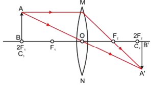
After tracing the path of a ray of light passing through a rectangular glass slab for four different values of the angle of incidence, a student reported his observations in tabular form as given below: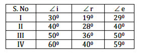
The best observation is:
I
II
III
IV
A.
I
For glass slab,
Refractive index of glass = 1.5
A student traces the path of a ray of light passing through a rectangular glass slab and marks the angle of incidence i, angle of refraction r and angle of emergence e, as shown: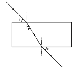
The correct marked angles are:


C.
Other angles are not taken with respect to normal.
In order to locate the image, any two rays can be chosen.
i) a ray which is parallel to the principal axis, after reflection will pass through the principal focus in case of a concave mirror and diverge from the principal axis in case of a convex mirror.
ii) A ray passing through the principal focus will emerge parallel to the principal axis after reflection.
When an object is placed between the centre of curvature and focus of a concave mirror, the ray diagram is as shown below:
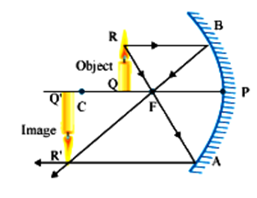
Given,
Object distance from the lens, u = - 8 cm
Focal length of the lens, f = 12 cm
Height of the object, h = 5 cm
Using the lens formula,
Putting the values,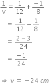
Thus, image is formed 24 cm on the left of the convex lens.
That is, object is formed on the same side of the object.
Now,
Magnification, m = 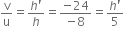
That is,
Height of the image, h' = 15 cm (positive)
Height of the image is 15 cm which is 3 times larger than the height of the object.
Therefore, the image formed is virtual, enlarged and erect.
The new cartesian signs for reflection of light is as given below:
1. The object is placed on the left side of the mirror. That is the incident light falls on the object from the left side.
2. All distances parallel to the principal axis is measured from the pole of the mirror.
3. All the distances which are measured to the right of the origin (along +x axis) is taken as positive whereas those measured to the left of the origin (along (-)ve x axis) is taken as negative.
4. Distances measure perpendicular to and above the principal axis (along +y axis) is taken as positive.
5. Distances measured perpendicular to and below the principal axis (along (-)ve y-axis) is taken to be negative.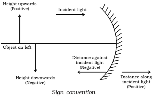
Given,
Magnification, m = 1/3
Object distance, u = -18 cm
Focal length, f = ?
Image distance, v = ?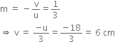
According to the mirror formula,
Since focal length is positive, it is a convex mirror.
Ray diagram: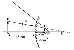
With the help of a ray diagram, state what is meant by refraction of light. State Snell’s law for refraction of light and also express it mathematically.
The refractive index of air with respect to glass is 2/3 and the refractive index of water with respect to air is 4/3. If the speed of light in glass is 2 x 10⁸ m/s, find the speed of light in:
a) air, b) water.
When a ray of light travels from one transparent medium to another, it bends at the surface. This happens because different media have different optical densities.
refraction of light is the phenomenon of bending of light as it travels from one medium to another is known as refraction of light.
When a ray of light moves from optically rarer medium to an optically denser medium, it bends towards the normal at the point of incidence.
Therefore, angle of incidence (i) is greater than the angle of refraction (r).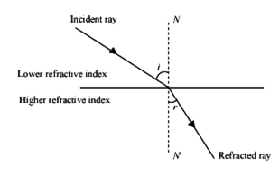
Snell's law states that, the ratio of the angle of incidence to the sine of the angle of refraction is constant.
Mathematically, it is given as,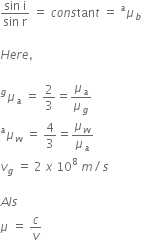
where,  is the absolute refractive index of a medium w.r.t vacuum
c is the speed of light in vacuum
v is the speed of light in medium
a) Now,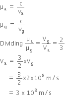
b) We have,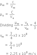
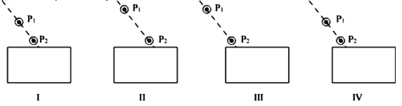
I
II
III
IV
C.
III
The student will get best results when the pins are placed as in figure III.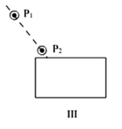
If you are to determine the focal length of a convex lens, you should have
A convex lens and a screen
A convex lens and a lens holder
A lens holder, a screen holder and a scale
A convex lens, a screen holder and a scale
D.
A convex lens, a screen holder and a scale
A convex lens, a screen holder for them and a scale are required in order to determine the focal length of a convex lens.
A student obtained a sharp inverted image of a distant tree on a screen placed in front of the concave mirror. He then removed the screen and tried to look into the mirror. He would now see,
a very blurred image on the wall opposite to the mirror
an erect and magnified image of the tree in the mirror
no image as the screen has been removed
a highly diminished inverted image of the tree at the focus of the mirror
D.
a highly diminished inverted image of the tree at the focus of the mirror
The student would observe a highly diminished inverted image of the tree at the focus of the mirror.
A student has to determine the focal length of a concave mirror by obtaining the image of a distant object on a screen. For getting best results he should focus,
a distant tree or an electric pole
a well-illuminated distant building
well-lit grills of the nearest window
a burning candle laced at the distant edge of the laboratory table
A.
a distant tree or an electric pole
In order to determine the focal length of a concave mirror, the student focus on a distant tree or an electric dpole
State any four characteristics of the image of an object formed by a plane mirror.
Characteristics:
1. The image is always virtual and erect
2. The image is formed behind the mirror
3. Image is of the same size as that of the object.
4. Image is formed at the same distance behind the mirror as the object is in front of the mirror.
An object is placed between infinity and the pole of a convex mirror. Draw a ray diagram and also state the position, the relative size and the nature of the image formed.
When an object is placed between the infinity and the pole of a convex mirror, then ray diagram for the formation of the image is as shown below: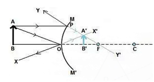
Position of the image: Between P and F and behind the mirror
Nature of the image: Virtual, erect and diminished.
What is the principle of reversibility of light? Show that the incident ray of light is parallel to the emergent ray of light when light falls obliquely on a side of a rectangular glass slab.
The principle of reversibility of light states that the light ray after reflection or refraction, when reversed, will retrace its path.
Using the Snell's law,
When light ray falls from a rarer to denser medium, then
n21 = 
When retraced, the ray will move from denser to rarer medium.
That is,
Therefore,
a) What is meant by the 'power of a lens'?
b) State and define the S.I. unit of power of a lens.
c) A convex lens of focal length 25 cm and a concave lens of focal length 10 cm are placed in close contact with each other.
Calculate the lens power of this combination.
a) The ability of a lens to converge or diverge a beam of the light ray is known as the Power (P) of the lens.
Power is equal to the reciprocal of the focal length.
That is, P = 
b) SI unit of the power of a lens is Dioptre.
1 diopter =  = 1 m-1
1 m is the focal length of the lens.
c) Given,
Focal length, f = +25 cm
= 

Focal length, f2 = -10 cm = 
Power, P2 = 
Power of the combination of lens, P = P1 + P2
P = 4 D - 10 D = - 6 D
To find the focal length of a concave mirror, Sita should choose which one of the following set-ups?
A mirror holder and a screen holder
A screen holder and a scale
A mirror holder, a screen holder and a scale
A screen, a mirror, holders for them and a scale
D.
A screen, a mirror, holders for them and a scale
By using a convex lens, a student obtained a sharp image of his class-room window grill on a screen. In which direction should he move the lens to focus a distant tree instead of the grill?
Towards the screen
Away from the screen
Very far away from the screen
Behind the screen
A.
Towards the screen
You have four test tubes, A, B, C and D containing sodium carbonate, sodium chloride, lime water and blue litmus solutions respectively. Out of these the material of which test tube/ test tubes would be suitable for the correct test of acetic/ethanoic acid?
only A
A and B
B and C
A and D
D.
A and D
The chemical reaction between ethanoic (acetic) acid and sodium carbonate is:
2CH3COOH + Na2CO3 → 2 CH3COONa + CO2 + H2O
On passing CO2 gas through lime water, the lime water turns milky. The milky appearance of lime water is due to the formation of solid calcium carbonate (CaCO3).
Reaction:
Ca(OH)2 + CO2 → CaCO3 + H2O
therefore, out of four test tubes A, B, C and D, only A and D test tubes would be suitable for the correct test of acetic/ethanoic acid.
Acetic acid also reacts with lime water to give calcium acetate (CH3COO)2Ca) as a product. But here it is not considered as a correct test of acetic/ethanoic acid.
Reaction:
2 CH3COOH + Ca(OH)2 → (CH3COO)2Ca + 2H2O
Hence, the correct answer is the option (d).
A gas is liberated immediately with a brisk effervescence when you add acetic acid to sodium hydrogen carbonate powder in a test tube. Name the gas and describe the test that confirms the identity of the gas.
When acetic acid (CH3COOH) is added to the sodium hydrogen carbonate (NaHCO3) than carbon dioxide gas produce with brisk effervescence.
CH3COOH + NaHCO3 →CH3COONa + CO2↑ + H2O
Observations: The gas turns lime water milky that confirms the identity of CO2 gas.
Ca(OH)2 + CO2 → CaCO3↓ + H2O
2 mL of sodium hydroxide solution is added to a few pieces of granulated zinc metal taken in a test tube. When the contents are warmed, a gas evolves which is bubbled through a soap solution before testing. Write the equation of the chemical reaction involved and the test to detect the gas. Name the gas which will be evolved when the same metal reacts with a dilute solution of a strong acid.
(i) Reaction is
(ii) The liberated H2 gas can be detected by burning matchstick at the opening of the test tube, it will burn with a pop sound with a blue flame.
(iii) When zinc reacts with dilute HCl it gives zinc chloride and hydrogen gas.
The pH of a salt used to make tasty and crispy pakoras is 14. Identify the salt and write a chemical equation for its formation. List its two uses.
NaHCO3 is used to make tasty and crispy pakoras.
Formation:
NaCl + H2O +CO2 + NH3 → NH4Cl + NaHCO3
Uses:
(i) For making baking powder
(ii) Used as antacids
Sponsor Area
Sponsor Area