Physics Part I Chapter 2 Electrostatic Potential And Capacitance
  • Sponsor Area

    NCERT Solution For Class 12 Physics Physics Part I

    Electrostatic Potential And Capacitance Here is the CBSE Physics Chapter 2 for Class 12 students. Summary and detailed explanation of the lesson, including the definitions of difficult words. All of the exercises and questions and answers from the lesson's back end have been completed. NCERT Solutions for Class 12 Physics Electrostatic Potential And Capacitance Chapter 2 NCERT Solutions for Class 12 Physics Electrostatic Potential And Capacitance Chapter 2 The following is a summary in Hindi and English for the academic year 2021-2022. You can save these solutions to your computer or use the Class 12 Physics.

    Question 1
    CBSEENPH12037292

    Two charges 5 x 10⁻⁸C and –3 x 10⁻⁸ C are located 16 cm apart. At what point(s) on the line joining the two charges is the electric potential zero? Take the potential at infinity to be zero.

    Solution
    Given, 
    Charge, q15×10-8 C
    Charge, q2=–3 x 10⁻⁸ C
    Distance between the two charges, d= 16 cm

    The possibility of point where total potential due to q
    1 and q2 is zero may be that point which lies out side the segment joining q1 and q2.


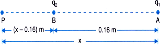
    Let required point P lies 'x' distance away from q1 and (x-0.16) distance away from q2 so that V1+V2 = 0.

    where, V1 is the potential at point P due to charge q1 and,
    V2 is the potential at point P due to charge q2. 
    Now, using the forlmula for electrostatic potential at a given point we get, 
                         
                         Kq1x+Kq2(x-0.16)=0
               
                 K5×10-8x-3×10⁻⁸(x-0.16) = 0

                             5x-3x-0.16 =0
                             
                             5x-0.8-3xx(x-0.16) = 0

                                     2x-0.8 = 0

                                        x=0.82                                     x = 0.4 m                                             = 40 cm

    That is, the required point is 40 cm away from  q1 and (40 – 16) = 24 cm from qsuch that, potential is 0.
    Question 2
    CBSEENPH12037293

    A regular hexagon of side 10 cm has a charge 5 μC at each of its vertices. Calculate the potential at the centre of the hexagon.

    Solution
    Given,
    Charge, q = 5 × 10-6CSide of hexagon, r = 10 cm  = 0.1 m 


    Potential at the centre of the hexagon is given by
                         V = 14πε0qr+qr+qr+qr+qr+qr    = 6×14πε0q/r V = 6×9×109×5×10-60.1 = 2.7 × 106 V.
    Question 3
    CBSEENPH12037294

    Two charges 2μC and –2μC are placed at points A and B, 6 cm apart.
    (a) Identify an equipotential surface of the system.
    (b) What is the direction of electric field at every point on this surface?

    Solution

    Given two charges placed at points A and B.
     q1 = 2μC = 2 × 10-6Cq2 = -2μc = -2×10⁻⁶Cr =6 cm= 0.06 m


    (a) Potential will be zero due to both charges at equipotential surface

       14πε0q1x+q2(0.06-x) =0

                    q1x = -q2(0.06-x)

             2×10⁻⁶x = --2×10⁻⁶(0.06)-x

                         x = 0.06 - x
                                 x=0.062 = 0.03 m

    i.e., the plane normal to AB and passing through its mid-point has zero potential everywhere.

    (b) The direction of electric field is normal to the plane in the AB direction.
    Question 4
    CBSEENPH12037295

    A spherical conductor of radius 12 cm has a charge of 1.6 x 10⁻⁷ C distributed uniformly on its surface. What is the electric fields
    (a) inside the sphere,
    (b)  just outside the sphere,
    (c) at a point 18 cm from the centre of the sphere?

    Solution

    Given,  
    Charge on conductor, q = 1.6 × 10-7C 

    Radius of spherical conductor, r = 0.12 m

    (a) Since, charge resides on the outer surface of the sphere, magnitude of electric field is 0 inside.

    (b) Electric field just outside the sphere is given by
                   
                          E = 14πε0qr2 = 9 × 109 × 1.6 × 10-7(0.12)2 = 105 NC-1

    (c) At a point 0.18 m from the centre of the sphere

                       E= 14πε0qr2   = 9 ×109 × 1.6 × 10-7(0.18)2   = 4.4 × 104 NC-1

    Question 5
    CBSEENPH12037296

    Three capacitors each of capacitance 9 pF are connected in series:
    (a) What is the total capacitance of the combination?
    (b) What is the potential difference across each capacitor if the combination is connected to a 120 V supply?

    Solution
    Given, three capacitors of value
           
                 C1 = C2 = C3 = 9pF      = 9 × 10-12F

    (a) Since the capacitors are connected in series.

    since, the capacitances are equal so


    Question 6
    CBSEENPH12037297

    Three capacitors of capacitances 2 pF, 3 pF and 4 pF are connected in parallel.
    (a) What is the total capacitance of the combination?
    (b) Determine the charge on each capacitor if the combination is connected to a 100 V supply.

    Solution

    Given, three capacitors of capacitances
                             C1 = 2 pF = 2 × 10-12 F
                             C2 = 3 pF = 3 × 10-12F
                             C3 = 4 pF = 4 × 10-12F

    (a) Since the capacitors are connected in parallel we have,
                          C = C1+C2+C3
                        = (2+3+4) × 10-12= 9 × 10-12 = 9 pF

    (b) Given,  Potential-V = 100 volt
                       
                        q1=C1V= 2 ×10-12 ×100= 2 × 10-10 C

                        q2 = C2V = 3×10-12×100= 3 × 10-10Cq3 = C3V= 4×10-12×100= 4 × 10-10C

    q1,q2 and q3 represent the charge on each capacitor respectively.


    Question 7
    CBSEENPH12037298

    In a parallel plate capacitor with air between the plates, each plate has an area of 6 x 10⁻³ mand the distance between the plates is 3 mm. Calculate the capacitance of the capacitor. If this capacitor is connected to a 100 V supply, what is the charge on each plate of the capacitor?

    Solution

    Given,                 Distance between the plates, d = 3 × 10-3 mArea of plates, A= 6 × 10-3 m2 
                               Capacitance, C = ε0Ad                                    = 8.854×10-12×6×10-33×10-3                                   = 18 × 10-12F = 18pF
    Here,
    Capacitor is connected to a voltage, V = 100 V
                       Charge on each place of the capacitor, q = CV                                                                                 = 18 × 10-12 × 100                                                                                = 1.8 × 10-9C

    Question 8
    CBSEENPH12037299

    Explain what would happen if in the capacitor given in Question 2.8, a 3 mm thick mica sheet (of dielectric constant = 6) were inserted between the plates,
    (a) while the voltage supply remained connected.
    (b) after the supply was disconnected.

    Solution

    (a)    Given,
    Dielectric constant of mica sheet, k  = 6
    Thickness ofmica sheet, t =3 mm = 3×10⁻³ m
                                     Capacitance of the plate, C = kC0                                                       = 6 × 18×10-12F                                                       = 108 × 10-12F                                                       = 108p F
    Using the formula Q=CV
                               = 108 × 10-12 × 100= 108 × 10-10
                            Q = 1.08 × 10-8C

    So, while voltage supply remained connected we have
    C = 108 pF   and Q = 1.08 × 10-8C

    (b) After the supply was disconnected, the charge remains same

    i.e.,                q = 1.8 × 10-9C
    and as                Q = CV
                           
                             V = QC     = 1.8 × 10-9108 × 10-12    = 16.66 V

    The charge remains constant i.e., Q = 1.08 x 10⁻⁸ C after the supply was disconnected and the voltage will come down to 16.6 V.

    Question 9
    CBSEENPH12037300

    A 12 pF capacitor is connected to a 50 V battery. How much electrostatic energy is stored in the capacitor?

    Solution

    Given,  
             Potential applied, V = 50 VCapacitance, C = 12 pF = 12 ×10-12 F

    Electrostatic energy stored in the capacitor is given as

                     U= 12CV2U= 12×12×10-12×(50)2
                 U = 1.5 × 10-8J.

    Question 10
    CBSEENPH12037301

    A 600 pF capacitor is charged by a 200 V supply. It is then disconnected from the supply and is connected to another uncharged 600 pF capacitor. How much electrostatic energy is lost in the process?

    Solution

     Given,      Voltage, V= 200 V Capacitance, C= 600 pF = 600 × 10-12FUsing the formula,  Q = CV                                       = 600 × 10-12 × 200
                         Q = 12 × 10-8C

    Electrostatic energy stored in capacitor

                U1 = 12CV2     = 12×600×10-12×(200)2 U1= 12 × 10-6J

    Now, the supply is disconnected and the capacitor is connected to another similar uncharged 600 pF capacitor.
    Therefore, the charge is divided equally between the two capacitors.

    Hence,
              Q1 = Q2 = 12 × 10-82 = 6 × 10-8C
    and
             V1 = V2 = Q1C1 = 6 × 10-8600 × 10-12 =  100 V

    Total capacitance, C = C1+C2
                               = 600 × 10-12F + 600 × 10-12F = 1200 × 10-12 F

    Now, the electrostatic energy stored is given as
                           U2 = 12CV2     = 12×1200×10-12×(100)2
                       U2 = 6 × 10-6J

    Electrostatic energy lost in the process
                                 = U1 - U2= 12 × 10-6 - 6 × 10-6 = 6 × 10-6J.
    Question 11
    CBSEENPH12037302

    A charge of 8 mC is located at the origin. Calculate the work done in taking a small charge of –2 x 10⁻⁹ C from a point P(0, 0, 3 cm) to a point Q(0, 4 cm, 0), via a point R (0, 6 cm, 9 cm).

    Solution

    Given,
    Charge, q =8 mC=8 x 10⁻³ C is located at origin and the small charge q0 =–2 x 10⁻⁹ C is taken from point P (0,0,3 cm) to a point Q (0,4 cm,0) through point R (0,6 cm,9 cm) as shown in the figure below.
    Initial separation between q0 and q is rp = 3 cm = 0.03 m
    Final separation between q0 and q is rQ = 4 cm = 0.04 m


    Work done in taking the charge q
    0 from point P to Q does not dependent on the path followed and depends only upon rp and rQ i.e., initial and final positions.
                     W = 14πε0qq01rQ-1rp        W = 9 × 109 × 8 × 10-3 × (-2×10-9) × 10.04-10.03     = 1.2 J.

    Note: Point R is irrelevant to the answer.

    Question 12
    CBSEENPH12037303

    A cube of side b has a charge q at each of its vertices. Determine the potential and electric field due to these charges array at the centre of the cube.

    Solution
    Given,
    Side of cube=b
    Charge on vertices of cube =q
    Diagonal DF of cube
                        DF = b2+b2+b2DF = b3
    Thus,           DO = DF2 = 32b 


    Due to one charge q the potential at the centre O is given by

                         V = 14πε0qr = 14πε0q3b2

    Due to eight charges the total potential at the centre O is given as,

    V = 814πε0q32b
          = 4q3πε0b

    Electric field at the centre of of cube:
    Due to two opposite corners D and F electric field intensity at the centre ‘O’ are equal in magnitude and opposite in direction. Therefore, they cancel out each other. Similarly all other intensities cancel out each other and the total electric field at centre is zero.
     
    Question 13
    CBSEENPH12037304

    Two tiny spheres carrying charges 1.5 μC and 2.5 μC are located 30 cm apart. Find the potential and electric field:
    (a) at the mid-point of the line joining the two charges, and
    (b) at a point 10 cm from this mid-point in a plane normal to the line and passing through the mid-point.

    Solution
    Given,
    Charge on 1st sphere, q1= 1.5 μC
    Charge on 2nd sphere, q2= 2.5 μC
    Distance between the two charges, r= 30 cm


    (a) Potential at the mid-point of the line joining the two charges is
                                           V = 14πε0q1r1+q2r2                   = 9 × 109 1.5 × 10-60.15+2.5 × 10-60.15V                   = 9 × 109 × 10-60.154                    = 240000
           V = 2.4 × 105V

    Electric field at the mid point O due to charge at A

    E = 14πε0q1r12   = 9 × 109 × 1.5 ×10-6(0.15)2   =  6 × 105 Vm-1 along OB

    Electric field at the mid-point O due to charge at B
    E = 14πε0q2r22    = 9 × 109 × 2.5 × 10-6(0.15)2   = 10 × 105 Vm-1 along OA 


    Thus, the total electric field at the mid-point O is


    E = 10 × 105 - 6 × 105    = 4 × 105Vm-1(along BA) 

    (b) Potential at the point C due to the two charges is

    V = 14πε0q1r1+q2r2where, r1 is the distance from A to C and,             r2 is the distance from B to Cr1=r2=(15)2+(10)2  =325  cm = 325 × 10-2 m   = 9×1091.5 × 10-6325×10-2+2.5 × 10-6325×10-2V   = 9×109×10-610-2. 4.0325V   = 9 × 418.02 × 105V    = 2 × 105 V

    Electric field at C due to charge at A


    Electric field at C due to charge at B

    E2 = 14πε0q2r22 = 9 × 109×2.5 × 10-6325 × 10-4 = 6.92 × 105 Vm-1

    If the angle between E1 and E2 be θ, then
    Using law of trignometry,
    tan θ=side opposite to angleperpendicular 

    tanθ2 = 0.150.10 = 1.5
      θ/2 = 56.3 °   or,    θ = 112.6°

    Thus, magnitude of resultant field at C is


    Question 14
    CBSEENPH12037305

    A spherical conducting shell of inner radius r1 and outer radius r2 has a charge Q.
    i) A charge q is placed at the centre of the shell. What is the surface charge density on the inner and outer surfaces of the shell?
    ii) Is the electric field inside a cavity (with no charge) zero, even if the shell is not spherical, but has any irregular shape? Explain.

    Solution

    A ‘+ q’ charge which is placed at the centre of the shell will induce a ‘–q’ charge on the inner surface of the shell.
    As a result of induction of '-q' on the inner surface, the charge on the outer surface will increase by '+q'. 
    Therefore, there will be total (Q + q) charge on the outer surface of the shell and, '–q' charge on the inner surface of the shell.


    i) Now,
    Surface are of inner sphere = 4πr12
    Surface area of outer sphere = 4πr22

    Thus,
    Charge density on the outer surface = Q+q4πr22
    and
    Charge density on the inner surface 
     = -q4πr12. 

    ii) As charge resides on the outer surface so, the net charge on the inner surface of the cavity is zero as per the Gaussian theorem. Although, the net charge is zero yet the electric field may not be zero if the cavity is not spherical because, the surface may not have equal number of positive and negative charges. 
    We assume a loop for this reason, some portion of which is inside the cavity and rest of its part is inside the conductor. Now, consider that there is some electric field inside the cavity. Since inside the conductor total electric field is zero and net work done by the field in bringing a test charge over this loop will not be zero. But this is not possible for an electrostatic field. Therefore, we must conclude that there is no electric field inside the cavity irrespective of its shape.

    Question 15
    CBSEENPH12037306

    i) Show that the normal component of electrostatic field has a discontinuity from one side of a charged surface to another given by
    (E2-E1). n^ = σε0
    where n^ is a unit vector normal to the surface at a point and σ is the surface charge density at that point. (The direction of n^ is from side 1 to side 2.) Hence, show that just outside a conductor, the electric field is σ n^/ε0.

    ii) Show that the tangential component of electrostatic field is continuous from one side of a charged surface to another. [Hint: Use the fact that work done by electrostatic field on a closed loop is zero.]

    Solution
    Consider that E1 and E2 be the electric field on the two sides of the charged surface and XY be the charged surface of dielectric as shown in the figure below.
    Note: Side 1 is the left side and side 2 is the right side.


    i) Near a plane sheet of charge, electric field is given as-E = σ2ε0 

    Electric field on side 2 if n^ is a unit vector normal to the sheet from side 1 to side 2-E2 =σ2ε0
    (In the outward direction normal to the side 2)
    Now, electric field on side 1 is-E1 = σ2ε0
    (In the outward direction normal to the side 1)


    As E1 and E2 are in opposite directions so will have opposite sign
              (E2-E1)n^ = σ2ε0--σ2ε0 = σε0n^

    There must be discontinuity at the sheet of charge since E
    1 and E2 act in opposite directions.
    Now, electric field inside the conductor vanishes.
    Hence, E1 = 0
    Therefore, electric field outside the conductor
                  E = E2 = σε0n^ 

    ii) Consider a rectangular loop ABCD of length l and negligible small breadth b. 
    Line integral along the closed path ABCD will be
           E.dl = E1.l - E2.l = 0  E1.l cos θ1 - E2 .l cos θ2  = 0(E1 cos θ1 - E2 cos θ2) . l = 0(E1' - E2') = 0  

    where, E1' and E2' are the tangential components of E1 and E2 respectively.
    Hence,             E’1 = E’2
    Therefore, the tangential component of the electrostatic field is continuous across the surface.

     
    Question 16
    CBSEENPH12037307

    A long charged cylinder of linear charged density λis surrounded by a hollow co-axial conducting cylinder. What is the electric field in the space between the two cylinders?

    Solution
    Two co-axial cylindrical shells A and B of radii 'a' and 'b' are possessed by a cylindrical capacitor. Assume, 'l' be the length of the cylindrical shell.

    Due to the introduction of +q charge on the inner cylindrical shell A, equal but opposite charge –q is induced on the inner surface of the outer cylindrical shell B. The induced charge +q on its outer surface will flow to earth if the shell B is earthed.


    The capacitance of the cylindrical capacitor is given as follows, if V is potential difference between the cylindrical shells A and B.

    C = qV 

    By applying the Gaussian theorem, we first need to find electric field E in the space between two shells to find out potential difference between the cylindrical shells A and B.
    Let a cylinder of radius 'r' (such that b > r > a) and length 'l' be the Gaussian surface. Charge enclosed by the Gaussian surface is λl.
    where, λ is the charge per unit length on the shell A.
    The electric flux will cross through only curved surface of the cylinder (Gaussian surface).

    As the area of curved surface of cylinder is 2πrl, we have by Gaussian theorem
               E. ds  = qε0E . 2πrl = λlε0i.e,     E = λ2πε0r 

    The field lines are radial and normal to the axis of charged cylinder. 
    Question 17
    CBSEENPH12037308

    In a hydrogen atom, the electron and proton are bound at a distance of about 0.53 Å:
    a) Estimate the potential energy of the system in eV, taking the zero of the potential energy at infinite separation of the electron from proton.
    b) What is the minimum work required to free the electron, given that its kinetic energy in the orbit is half the magnitude of potential energy obtained in (a)?
    c)What are the answers to (a) and (b) above if the zero of potential energy is taken at 1.06 A separation?

    Solution

    Given,
                     Charge on an electron, q1 = -1.6 × 10-19C  Charge on a proton, q2 = 1.6 × 10-19 CDistance between electron and proton, r = 0.53 Å = 0.53 × 10-10m
     
    a) Potential energy  = 14πε0q1 q2r
                                     = 9 × 109 -1.6 × 10-19 1.6 × 10-190.53 × 10-10J= -43.47 × 10-19 J

    = -43.47 × 10-191.6 × 10-19eV = -27.17 eV

    Potential energy is zero at infinite separation.
    Hence, the potential energy of the system is (–27.17–0) or 27.17 eV if zero of potential energy is taken at infinite separation.

    b) Kinetic Energy of electron is given by

    12Potential Energy =27.22=13.6 eV

     Total energy of electron = -27.2 + 13.6
                                          = - 13.6 eV

    Amount of work required to free the electron = Increase in energy of electron
    = 0 – (–13.6)
    = 13.6 eV

    c) If the zero of Potential Energy is taken at 1.06 Å (1.06 x 10⁻¹⁰ m) separation, then the potential energy of system 
          P.E = 9 × 1091.6 × 10-19 × 1.6 × 10-191.06 × 10-10    = 21.74 × 10-19J    = - 21.74 × 10-191.6 × 10-19       = -13.585 eV

    The amount of work done to free the electron in this case is,

    =  -27.17 - (-13.585)= - 13.585 eV


    Sponsor Area

    Question 18
    CBSEENPH12037309

    If one of the two electrons of a H2 molecule is removed, we get a hydrogen molecular ion H2+. In the ground state of a H2+, the two protons are separated by roughly 1.5Å, and the electron is roughly 1 Å from each proton. Determine the potential energy of the system. Specify your choice of the zero of potential energy.

    Solution
    Let us consider the distance between two protons pand p2 as r12 and,
    Distance of electron(e-) from each proton p1 and pbe r13 and r23. 


    Given,           
    r12 = 1.5 Å = 1.5 × 10-10 m  r13 = r23 = 1Å = 10-10 m Charge on proton, q1 = q2 = 1.6 × 10-19C Charge on electron, q3 = -1.6 × 10-19C  

    Now, the potential energy of the system

    P.E= 14πε0q1q2r12+q1q3r13+q2q3r23
                                     = 9 × 1091.6 ×10-19×1.6×10-191.5 × 10-10+1.6×10⁻¹⁹×-1.6×10-1910-10+1.6 × 10-19×-1.6 × 10-1910-10
           = 1.6 × 10-19 × 1.6 × 10-19 × 9 × 10910-1011.5-11-11       = 1.6 × 1.6 × 9 × 10-19-19+9+1023-2       = -2.56 × 9 × 10-19 × 43 = -2.56 × 12 × 10-19J       = -2.56 × 12 × 10-191.6 × 10-19eV       = -1.6 × 12 eVP.E= - 19.2 e V

    The zero Potential Energy is taken to be at infinity.
    Question 19
    CBSEENPH12037310

    Two charged conducting spheres of radii a and b are connected to each other by a wire. What is the ratio of electric fields at the surfaces of the two spheres? Use the result obtained to explain why charge density on the sharp and pointed ends of a conductor is higher than on its flatter portions.

    Solution
    Let, the charge possessed by two conducting spheres of radii a and b be qand qrespectively.

    Potential on the surface of first sphere, V1=14πε0.q1a

    Potential on the surface of second sphere, V2=14πε0.q2b

    Till the potentials of two conductors become equal the flow of charges continue.
                               V1 = V2

              14πε0.q1a = 14πε0.q2b

                   q1q2 = ab 
    Now, 
    Electric field on sphere 1, E1=14πε0.q1a2 

    Electric field on sphere 2, E2=14πε0.q2b2 

    E1E2 = q1q2. b2a2 = ab. b2a2 = ba

    Therefore, the ratio of the electric field of first sphere to that of the second sphere is b:a.

    The surface charge densities of the two spheres are given as


    This implies,
    The surface charge densities are inversely proportional to the radii of the sphere.
    The surface charge density on the sharp and pointed ends of a conductor is higher than on its flatter portion since a flat portion may be taken as a spherical surface of large radius and a pointed portion as that of small radius.

    Question 20
    CBSEENPH12037311

    Two charges –q and +q are located at points (0, 0, -a) and (0, 0, a), respectively.
    What is the electrostatic potential at the points (0, 0, z) and (x, y, 0)?

    Solution
    Given,
    two charges -q and +q are located at (0,0,-a) and (0,0,a) respectively.
    We have to find electrostatic potential at (0,0,z) and (x,y,0) [see fig. given below].


    Electrostatic potential at point P(0,0,z) when closer to charge +q  is given by:


    where p = q.(2a) is the dipole moment.

    Electrostatic potential at P(0,0,z) when closer to charge -q is given by [see fig. below] :


    So potential at point P (0, 0, ± z) is
                 V = ±14πε0. p(z2-a2)

    Now, Electrostatic potential at point (x, y, 0 ) is


    Therefore, Electrostatic potential at point (x,y,0) is equal to 0.


    Question 21
    CBSEENPH12037312

    Two charges –q and +q are located at points (0, 0, -a) and (0, 0, a), respectively.
    Obtain the dependence of potential on the distance r of a point from the origin when r / a >>1.

    Solution
    Given,
    Two charges -q and +q are located at (0,0,-a) and (0,0,a) respectively.


    Electric potential at a distance OP=r from the origin is given by:


    ∴ the potential is inversely proportional to r2, when r a 1.


    Question 22
    CBSEENPH12037313

    Two charges –q and +q are located at points (0, 0, -a) and (0, 0, a), respectively.
    How much work is done in moving a small test charge from the point (5, 0, 0) to (-7, 0, 0) along the x-axis? Does the answer change if the path of the test charge between the same points is not along the x-axis?


    Solution

    Given,
    Two charges -q and +q are located at (0,0,-a) and (0,0,a) respectively.

    To find: the amount of work done to move a small test charge from point (5,0,0) to (-7,0,0) along x-axis.

    Electrostatic potential at point (5, 0, 0) due to the dipole is given as


    Electrostatic potential at point (–7, 0, 0) due to the dipole is given as

    In moving small test charge q from the point (5, 0, 0) to (–7, 0, 0) the work done W = q(V1– V2) = q x 0 = 0.

    The work done by the electrostatic field between two points is not dependant on path connecting two points. Therefore, work done by any charge along X axis, Y axis or on equitorial plane is zero as the potential does not change.

    Question 23
    CBSEENPH12037314

    Figure shows a charge array known as an electric quadrupole. For a point on the axis of the quadrupole, obtain the dependence of potential on r for r/a >> 1, and contrast your results with that due to an electric dipole, and an electric monopole (i.e., a single charge).


    Solution


    Potential at P, due to charge +q at A= 14πε0qr+a
    Potential at P, due to charge -2q at B= 14πε0-2qr
    Potential at P, due to charge +q at C= 14πε0qr-a

    Total electrostatic potential at P


    Question 24
    CBSEENPH12037315

    An electrical technician requires a capacitance of 2 μF in a circuit across a potential difference of 1 kV. A large number of 1 μF capacitors are available to him each of which can withstand a potential difference of not more than 400 V. Suggest a possible arrangement that requires the minimum number of capacitors.

    Solution

    Here we have,
    Total required capacitance, C = 2μF 
    Potential difference applied across the circuit, V =1 kV= 1000 V
    Capacitance of each capacitor, C1 = 1μF 
    Maximum Potential difference applied across each capacitor, V1 = 400 V 

    Let, the possible arrangement of circuit be such that n capacitors of 1μF each, be connected in series in a row and m such rows be connected in parallel.

    Therefore, total number of capacitors-N = m x n

    Since the potential in each row is 1000 V, the number of capacitors in each row of series arrangement is 
                  
                         1000n = 400        n = 2.5

    Since, the number of capacitors cannot be in fraction, therefore, we take n=3.

    Now, the capacitance of n capacitors in series, in m such rows is

    1Cs = 1n+1n+...n lines = mCs = 1nμF

    So, the resultant capacitance of all capacitors is equal to
     
    1n+1n+1n....+m terms = 2μF
                               mn=2 μF
                         
                                m3=2m = 6 rowsn = 6 × 3 = 18

    Hence, 1μF capacitor each,  should be connected in 6 parallel rows, where,  each row contains 3 capacitors each in series.

    Question 25
    CBSEENPH12037316

    What is the area of the plates of a 2F parallel plate capacitor, given that the separation between the plates is 0.5 cm? [You will realise from your answer why ordinary capacitors are in the range of μF or less. However, electorlytic capacitors do have a much larger capacitance (0.1 F) because of very minute separation between the conductor.]

    Solution
    Given,
    Capacitance of parallel plate capacitor, C=2F
    Seperation between the parallel plate capacitor, d =0.5 cm =5 x 10
    –3 m

    Now, using the formula for capacitance of a parallel plate capacitor,
                 C = ε0AdA = Cdε0                                      (ε0 =8.85 × 10-12 Fm-1)
       = 2×5×10-38.85 × 10-12

    A = 1.13 × 109 m2    = 1.13 × 103 km2 = 1130 km2

    Therfore, inorder to get the capacitance in Farads, the area of the plates should be in kilometres which, practically cause inconvenience. And, that is why, the ordinary capacitors are in the range of μF.

    .
    Question 26
    CBSEENPH12037317

    Obtain the equivalent capacitance of the network shown in figure below. For a 300 V supply, determine the charge and voltage across each capacitor.

    Solution
    Given,
    Potential applied across the network, V=300 V
    Capacitance on capacitor 1, C1=100 pF
    Capacitance on capacitor 2, C2=200 pF
    Capacitance on capacitor 3, C3=200 pF
    Capacitance on capacitor 4, C4=100 pF

    A similar network is shown below as given in the problem.


    Assume, that the series combination of C2 and C3 is C23.

     1C23 = 1C2+1C3 = 1200+1200 = 1100

      C23 = 100pF

    Suppose, the parallel combination of C1 and C23 is C’. Then,

    C' = C1+C23 = 100+100 = 200pF 

    Let, the series combination of C4 and C is C.

     
    1C = 1C4+1C' = 1100+1200=3200 
     
      C = 2003pF

    Therefore, total charge on all capacitors.

    q=CV  =2003×10-12×300  =2 × 10-8 C V4=q4C4=2×10-8100×10-12     V4 = 2×100= 200 VV1= [300-200] =100 Vq1= C1V1=100×10-12×100=10-8 C V2=V3 V2 + V3 = 100 V2 V2= 100V2= 50 Vq2=C2V2 = 200×10-12×50     = 10000 ×10-12= 10-8 Cq3 = C3V3 =200× 1012× 50 =10-8 C  
     
    Hence, the charge and voltage across each capacitor is as given below :


    Question 27
    CBSEENPH12037318

    The plates of a parallel plate capacitor have an area of 90 cm2 each and are separated by 2.5 mm. The capacitor is charged by connecting it to a 400 V supply.
    (a) How much electrostatic energy is stored by the capacitor?
    (b) View this energy as stored in the electrostatic field between the plates, and obtain the energy per unit volume u. Hence arrive at a relation between u and the magnitude of electric field E between the plates.

    Solution

    Given,  
    Area of the parallel plate capacitor, A=90 cm290 × 10-4 m 
    Distance between the parallel plates, d=2.5 mm = 2.5 × 10-3 m
    Potential applied across the capacitor, V= 400 V

    (a) Electrostatic energy stored in the capacitor, U
           
                  U = 12CV2     = 12ε0AdV2    = 128.85 × 10-12 90 × 10-4 (400)22.5 × 10-3    = 8.85 × 90 × 162 × 2.5×10-9    = 2.55 × 10-6J 

    (b) Volume of the medium in between the plates
                                = A × d= 90 × 10-4 × 2.5 × 10-3= 225 × 10-7m3

    Energy stored per unit volume, u =2.55 × 10-6225 × 10-7
                                                u = 0.113 Jm-3

    So, relation between magnitude of electric field and u
              
             u = UA. d = 12CV2A. d = 12V2A .dε0Ad  C=εA/d             

                           u = 12ε0 V2d2          

                          U = 12ε0E2             [E = Vd]

    Question 28
    CBSEENPH12037319

    A 4 μF capacitor is charged by a 200V supply. It is then disconnected from the supply, and is connected to another uncharged 2 μF capacitor. How much electrostatic energy of the first capacitor is lost in the form of heat and electromagnetic radiation?

    Solution

    Given, a 4 μF capacitor is charged by a 200 V supply.
    Then,
    Charge on the capacitor-Q= CV
                                        = 4 x 10–6 x 200

                                        = 8 x 10⁻⁴ C

    Also given, it is then disconnected and, connected to another uncharged 2μF (2 × 10-6 F) capacitor. 
    Thus, total capacitance-C'= (4 + 2)μF =6 μF

    Until both the capacitor acquire a common potential, charge on the first capacitor is shared between them.
    After the combination, the common potential-V' =Q/C
               V' = 8 × 10-4C6 × 10-6F = 1.33 × 102VV' = 133 V 

    Electrostatic energy of the first capacitor, before the combination,
                U1 = 12CV2 = 124×10-6 2002U1 = 8 × 10-2J

    Electrostatic energy of the system, after the combination,
    U2 = 12C'V'2 = 126×10-6 (133)2U2 = 5.30 × 10-2J

    Now, electrostatic energy lost by the first capacitor in the form of heat and electromagnetic radiation is

                       U = U1-U2     = (8×10⁻²-5.3 × 10-2)    = 2.7 × 10-2J


    Question 29
    CBSEENPH12037320

    Show that the force on each plate of a parallel plate capacitor has a magnitude equal to 12 QE,  where Q is the charge on the capacitor, and E is the magnitude of electric field between the plates. Explain the origin of the factor 1/2.

    Solution
    Let,
    Surface charge density of the capacitor= σ
    Area of cross-section of the plate= A
    Using the formula of charge on capacitor
                        Q = σA
                and    E = σ/ε0       or    ε0 = σE           ...(i)

    If, the separation of the capacitor plates is increased by a small distance x against the force F, then, work done by the external agency = F.Δx


    Let u be the energy stored per unit volume or the energy density of capacitor, then, increase in the potential energy of the capacitor is,

                         = u×increase in volume= u× A . x

              F.x = uA. x       F = uA          = 12ε0E2A
                     
                       F=12σEE2A                    [From (i)]
                     
                        = 12σAE= 12QE

    Therefore, the origin of the factor 12 lies in the fact that field is zero just outside the conductor and it is E inside. Hence, the average value E/2 contributes to the force.

    Question 30
    CBSEENPH12037321

    A spherical capacitor consists of two concentric spherical conductors, held in position by suitable insulating supports. Show that the capacitance of a spherical capacitor is given by
    C = 4πε0r1r2r1-r2
    where r1 and r2 are the radii of outer and inner spheres respectively.


    Solution
    We are given two concentric spheres. The radii of the outer and inner sphere are r1 and r2 respectively.
    A charge -Q is introduced on the inner sphere, which, gets uniformly distributed on its outer surface. As a result, charge +Q is induced on the sphere's outer surface of radius r1 and Q on it's inner surface. Since, the outer surface is earthed, the positive charge will flow into earth.


    Electric field inside sphere of radius r
    2 is zero because of electrostatic shielding.

    i.e.,  E = 0  for  r < r2E = 0  for r > r1 

    Electric field exists in between and is directed radially outward.

    Electrostatic potential of inner sphere of radius r
    2
    V = 14πε0Qr2-Qr1 = Q4πε01r2-1r1 

    Electrostatic potential of outer sphere of radius r1= 0

    Potential difference-V  = Q4πε01r2-1r1

    If, C is the capacitance of spherical capacitor


    C = QV    = QQ4πε01r2-1r1C= 4πε0 r1 r2r1-r2
     
    Question 31
    CBSEENPH12037322

    A spherical capacitor has an inner sphere of radius 12 cm and an outer sphere of radius 13 cm. The outer sphere is earthed and the inner sphere is given a charge of 2.5 μC. The space between the concentric spheres is filled with a liquid of dielectric constant 32.
    (a) Determine the capacitance of the capacitor.
    (b) What is the potential of the sphere?
    (c) Compare the capacitance of this capacitor with that of an isolated sphere of radius 12 cm. Explain why the latter is much smaller.

    Solution
    Given, a spherical capacitor consisting of two concentric sphere.
    Radius of inner sphere-r1= 12 cm=12 × 10-2 m
    Radius of ouer sphere-r2= 13 cm =13 × 10-2m
    Charge on inner sphere-q=  2.5 μC = 2.5  × 10-6C
    Dielctric constant of liquid-k = 32


    (a)Using the formula, 

                       C = kC0C = k.4πε0r1r2r2-r1

    = 32 × 13 ×10-2 × 12 × 10-29 × 10913 × 10-2 -12 × 10-2              4πε0 = 19 × 109

    = 32 × 13 × 129×10-11 = 16443×10-11 = 5.54 × 10-9F 

    (b) Potential of inner sphere,
              
             V = qC    = 2.5 × 10-65.54 × 10-9    = 4.5 × 102V 

    (c) Capacitance of isolated sphere of radius r=12 cm
           
             C = 4πε0   = 12 × 10-29 × 109    = 1.33 × 10-11F 

    The potential in case of two concentric spheres is distributed over both the spheres. This implies, the potential difference between the two concentric spheres becomes smaller. And, because the capacitance is inversely proportional to the potential difference (C=QV), the capacitance of two concentric spheres is much larger than the capacitance due to an isolated sphere.

    Question 32
    CBSEENPH12037323

    Answer carefully:
    a) Two large conducting spheres carrying charges Q1 and Q2 are brought close to each other. Is the magnitude of electrostatic force between them exactly given by Q1 Q2 /4πε0r2, where r is the distance between their centres?

    Solution
    The charges are not exactly point charges in this case. And since, the large conducting spheres have been brought closer, the charge distribution will no longer remain uniform. Thus, the magnitude of electrostatic force between the two spheres cannot be given by Q1Q24πεr2 .
    Question 33
    CBSEENPH12037324

    Answer carefully:
    If Coulomb's law involved 1/r3 dependence (instead of 1/r2), would Gauss's law be still true?

    Solution

    The dependance of solid angle on  radius 'r' is given by

     = ds cosθr2  and not equal to dscosθr3.

    Solid angle is that angle an arbitary area makes at a point P.
    Gauss's law which happens to be an equivalent of Coulomb's law will not hold true if, Coulomb's law involved 1/r3 dependance instead of 1/r2 dependance.

    Question 34
    CBSEENPH12037325

    Answer carefully:
    A small test charge is released at rest at a point in an electrostatic field configuration. Will it travel along the field line passing through that point?

    Solution
    The small test charge will traverse along the line of force only if the field line is a straight line. Here, since the initial velocity of the test charge is 0, it shall travel along the field line passing through that point. 


    Question 35
    CBSEENPH12037326

    Answer carefully:
    What is the work done by the field of a nucleus in a complete circular orbit of the electron? What if the orbit is elliptical?

    Solution
    The initial and final position for any complete orbit is same and hence W=0. Electron will remain in the same energy state.
    No matter what is the shape of the orbit, work done for any complete orbit is always zero.
    Question 36
    CBSEENPH12037327

    Answer carefully:
    We know that electric field is discontinuous across the surface of a charged conductor. Is electric potential also discontinuous there?

    Solution
    Electric potential is not discontinuous across the surface of a charged conductor. Since, electric potential is a scalar quantity and, does not have to represent directions, it is continuous at every point.
    Question 37
    CBSEENPH12037328

    Answer carefully:
    What meaning would you give to the capacitance of a single conductor?

    Solution
    The behaviour of a single conductor is like a capacitor with the second plate at infinity. Therefore, the capacitance of a single conductor is the amount of charge required to raise the potential of the conductor by a unit amount.
                             
                                  C=QV
    Question 38
    CBSEENPH12037329

    Answer carefully:
    Guess a possible reason why water has a much greater dielectric constant (= 80) than say, mica (= 6).

    Solution
    Water possess a permanent dipole moment of ~0.6×10⁻²⁹ cm and, has a high degree of assosciation of water molecules. Consequently, water has a greater dielcric strength (=80) than mica (=6).
    Question 39
    CBSEENPH12037330

    A cylindrical capacitor has two co-axial cylinders of length 15 cm and radii 1.5 cm and 1.4 cm. The outer cylinder is earthed and the inner cylinder is given a charge of 3.5 μC. Determine the capacitance of the system and the potential of the inner cylinder.
    Neglect end effects (i.e., bending of field lines at the ends).

    Solution

    Given, a cylindrical capacitor has two co-axial cylinders, of which, the outer cylinder is earthed.

    Length of cylinder-l= 15 cm = 15 × 10-2m
    Radius of inner cylinder-a = 1.4 cm= 1.4 × 10-2m
    Radius of outer cylinder-b = 1.5 cm= 1.5 × 10-2 m
    Charge on the inner cylinder-q =3.5 μC = 3.5 ×10-6C

    Capacitance of the sysyem=
                       
                    C = 2πε0l2.303log10(b/a)

                   = 2 × π × 8.854 × 10-12 × 15 × 10-22.303 log101.5 × 10-21.4 × 10-2
                C = 1.21 × 10-10F

    Since, the outer cylinder is earthed the potential of inner cylinder will be equal to the potential difference between inner and outer cylinder.

    Hence, potential of inner cylinder
                           
                       V = qC     = 3.5 × 10-61.21 × 10-10     = 2.89 × 104 V.


    Sponsor Area

    Question 40
    CBSEENPH12037331

    A parallel plate capacitor is to be designed with a voltage rating 1 kV, using a material of dielectric constant 3 and dielectric strength about 107 Vm–1. (Dielectric strength is the maximum electric field a material can tolerate without breakdown, i.e., without starting to conduct electricity through partial ionisation.)
    For safety, we should like the field never to exceed, say 10% of the dielectric strength. What minimum area of the plates is required to have a capacitance of 50 pF?

    Solution

    Given,
    Voltage rating for the design of parallel plate capacitor-V= 1 KV=1000 V 
    Dielectric constant of material-K=εr= 3
    dielectric strength of material   = 107 V/m

    For safety, electric field at the most should be 10% of dielectric strength.
           E=10% of 107
                = 10100 V/m
               
              E= 106 V/m

    Area of the plates-A = ?
    Capacitance of plates-C=  50 pF = 50 × 10-12F

    Now, using the formula 
    E = Vd         
    ∴              d = VE    = 103106    = 10-3 m 

    Therefore,  C = ε0εrAd

                 A = Cdε0εr    = 50 × 10-12 × 10-38.85 × 10-12 × 3

                A = 1.9 × 10-3 m2

    Hence, the minimum area of plates required is 1.9 × 10-3 m2 .

    Question 41
    CBSEENPH12037332

    Describe schematically the equipotential surfaces corresponding to a constant electric field in the z-direction.

    Solution
    Equipotential surfaces are the surfaces where the potential has a constant value. 
    When an electric field acting in z-direction is constant, the potential in a direction perpendicular to z-axis remains constant. Therefore, equipotential surface is represented by the planes parallel to x-y plane.


    Question 42
    CBSEENPH12037333

    Describe schematically the equipotential surfaces corresponding to a field that uniformly increases in magnitude but remains in a constant (say, z) direction.

    Solution
    The surfaces where the potential has a constant value are called equipotential surfaces.
    The potential in a direction perpendicular to the direction of field remains constant irrespective of the magnitude of the field. Hence, equipotential surface would correspond to planes parallel to x-y plane. The seperation between the planes decrease for same potential difference.


    Question 43
    CBSEENPH12037334

    Describe schematically the equipotential surfaces corresponding to a single positive charge at the origin.

    Solution
    The surfaces where the potential has a constant value are called equipotential surfaces.
    The equipotential surfaces corresponding to a single charge at the origin are concentric spheres centered at the origin. With increase in distance from the origin, seperation between the equipotential also differ.

    Question 44
    CBSEENPH12037335

    Describe schematically the equipotential surfaces corresponding to uniform grid consisting of long equally spaced parallel charged wires in a plane.

    Solution
    The surfaces where the potential has a constant value are called equipotential surfaces.
    Near the grid, the equipotential surfaces are of periodically varying shape which gradually reach the shape of planes parallel to the grid at a certain distance.


    Question 45
    CBSEENPH12037336

    In a Van de Graaff type generator a spherical metal shell is to be a 15 x 105 V electrode. The dielectric strength of the gas surrounding the electrode is 5 x 10⁷ Vm–1. What is the minimum radius of the spherical shell required? (You will learn from this exercise why one cannot build an electrostatic generator using a very small shell which requires a small charge to acquire a high potential.)

    Solution
    Given,
    Dielectric strength of gas surrounding the electrodes-E = 5 x 10
    7 V / m.
    Potential of spherical metal shell-V = 15 x 105 V

    For spherical shell,    V = 14πε0qr
    As                           V = k qR              ... (i)                       
                                  E = k qR2              ... (ii)

    On dividing the above equations, we get,

                                  E = VR           [ from i and ii]

                                  R = VE     = 0.3 m      = 30 cmR = 15 × 10510% of 5 × 107R = 15 × 10510100×5×105×100   = 310 mR = 30 cm .

    Minimum radius of the spherical shell required-r = 30 cm.
    Question 46
    CBSEENPH12037337

    A small sphere of radius r1 and charge q1 is enclosed by a spherical shell of radius rand charge q2. Show that if q1 is positive, charge will necessarily flow from the sphere to the shell (when the two are connected by a wire) no matter what the charge q2 on the shell is.

    Solution
    Potential of inner sphere due to charge q1-V1 = 14πε0q1r1

    Potential of inner sphere due to the enclosed sphere-V2 = 14πε0q2r2

    Thus, total potential of inner sphere = V
    1 + V2
                         V = 14πε0q1r1+q2r2

    Potential of shell-V' = 14πε0q2r2

    Potential difference between inner sphere and shell= V – V’
          = 14πε0q1r1+q2r2-14πε0q2r2= 14πε0q1r1

    Therefore, q1 is positive as seen from the above equation.

    Since, from the above equation, potential difference does not depend on q2 we can conclude that, the charge will always flow from the sphere to shell, no matter whatsoever charge is on the shell.

    Question 47
    CBSEENPH12037338

    Why does the electric field inside a dielectric decrease when it is placed in an external electric field?

    Solution
    The external field induces dipole moment by stretching or re-orienting the molecules of dielectric. Net effect of these induced molecular dipole moment is the production of a field that opposes the external field. So, dielectric gets polarised in opposite direction and, electric field inside dielectric decreases.
    Question 48
    CBSEENPH12037339

    No work is done in moving test charge over an equipotential surface. Why?

    Solution
    If, a positive test charge q is moved from point A to B, then,
                     VB-VA= WABq
    where, WAB is work done to move charge q from A to B.
    Since, two points A and B are on the same equipotential surface,
                          
                       VB-VA=0
                      WAB= 0
    Question 49
    CBSEENPH12037340

    What is the work done in moving a test charge q through a distance of 1 cm along the equatorial axis of an electric dipole?

    Solution
    Work done is given by,
                           W = qV
    Since, the equitorial plane is also equipotential, we have,
                            Veq=0

    Therefore, work done in moving a positive test charge q through a distance of 1 cm is,
                             W=0
    Question 50
    CBSEENPH12037341

    What is the shape of the equipotential surfaces for a uniform electric field?

    Solution
    In a uniform electric field, the equipotential surfaces are perpendicular to the direction of electric field.
    The below fig. represents the shape of equipotential surfaces for uniform electric field.


    Question 51
    CBSEENPH12037342

    Define the term ‘potential energy’ of charge ‘q’ at a distance ‘r’ in an external electric field. 

    Solution
    Potential energy of charge 'q' at a distance 'r' in an external field, is defined as the amount of work done in order to move a charge 'q' from infinity to a particular point in the presence of external field.
    This work done, is stored in the form of potential energy.
                             P.E =  q.V (r)

    Question 52
    CBSEENPH12037343

    What is the shape of the equipotential surfaces for an isolated point charge?

    Solution
    The equipotential surfaces, for an isolated point charge are concentric spheres whose centres are located at the given point charge.


    Question 53
    CBSEENPH12037344

    A 500 μC charge is at the centre of a square of side 10 cm. Find the work done in moving a charge of 10 μC between two diagonally opposite points on the square.

    Solution

    Work done is given by q(v2-V1). 
    The two diagonally opposite points on a square has the same potential. Since, there is no difference in potential, work done is 0.
    Question 54
    CBSEENPH12037345

    What is the order of capacitances used in power supplies?

    Solution
    The capacitors used in power supplies varies in the order of micro-Farad.
    It is usually 1μF to 10 μF.
    Question 55
    CBSEENPH12037346

    Define the term ‘dielectric constant’ of a medium in terms of capacitance of a capacitor.

    Solution
    Dielctric constant is defined as the ratio of capacitance with dielectric medium in between the capacitor plates to the capacitance with vaccum in between the capacitor plates.
    Question 56
    CBSEENPH12037347

    Where does the energy of a capacitor reside?

    Solution
    The energy of a capacitor resides in between the medium seperating the two plates.
    Question 57
    CBSEENPH12037348

    What is meant by capacitance? Give its SI unit.

    Solution
    Capacitance is the ratio of electric charge stored on any of the plates of the capacitor to the electric potential between two plates of the capacitor.
    The SI unit of capacitance is farad.
    Question 58
    CBSEENPH12037349

    Define electric potential at a point in an electric field.

    Solution
    Electric potential at a point in an electric field, is defined as the amount of work done in order to move a unit positive charge from infinity to that point along any path, against the electrostatic forces, with acceleration zero.
    Question 59
    CBSEENPH12037350

    What will be the effect on capacity of a parallel plate condenser when area of each plate is doubled and distance between them is also doubled?

    Solution
    Capacitance is given by-C=εAd
    where, A is the area of cross-section,
    d is the distance between two plates.

    When, area of each plate is doubled and distance between them is also doubled,
    Capacitance-C=ε2A2d

    The factor 2 cancels out each other. This implies, capacitance remains unaffected.
    Question 60
    CBSEENPH12037351

    Write the formula for capacity of a parallel plate air capacitor with a metal sheet of thickness t in between the plates.

    Solution
    Capacity of a parallel plate capacitor with a metal sheet of thickness 't' in between the plates is given by,
                             C = 0Ad-t

    where, 'A' is the rea of cross-section of plates
    'd' is the distance between the plates, and
    't' is the thickness of metal plate.
    Question 61
    CBSEENPH12037352

    What are the expressions for energy of a charged capacitor?

    Solution
    Energy of a charged capacitor is given by the expressions below:

    E = 12QV = 12Q2C = 12CV2

    where,
    Q is charge on the plates,
    V is the potential applied between the plates, and
    C is the capacitance of the capacitor.

    Question 62
    CBSEENPH12037353

    A capacitor is charged through a potential difference of 200 V, when 0.1 C charge is stored in it. How much energy will it release, when it is discharged?

    Solution

    Given, 
    Potential difference across the capacitor-V = 200 V
    charge stored in the capacitor-q = 0.1 C

    Energy released on discharging = energy stored on charging = 12qV 
                =12×0.1×200 = 10 J.

    Question 63
    CBSEENPH12037354

    On inserting a dielectric between the plates of a capacitor, its capacitance is found to increase 5 times. What is the relative permittivity of the dielectric?

    Solution
    Given, capacitance increases by a factor of 5 on inserting a delectric between the plates of a capacitor.
    Relative permittivity of the dielectric is given by.

                        εr = k = CC0 = 5
    Question 64
    CBSEENPH12037355

    Write an expression for potential V(r) at a point due to two point charges q1 and qat position r1 and r2 respectively.

    Solution
    The potential at a point due to two point charges is given by,

            V(r) = 14πε0q1r1-r2+14πε0q2r1-r2 

    where,
    V(r) is the potential,
    q1 and q2 are two point charges, 
    r1 and rrepresnt the positions of point charges.
    Question 65
    CBSEENPH12037356

    Does the electric potential increase or decrease along the electric line of force?

    Solution
    Along the electric line of force, electric potential decreases.
    Question 66
    CBSEENPH12037357

    Is electric potential at any point in space necessarily zero if intensity of electric field at that point is zero?

    Solution
    Electric potential necessarily need not be 0 if the electric field at that point is zero. For instance, at a point mid-way between two equal and similar charges, the electric field strength is zero but the electric potential is not zero. 
    Question 67
    CBSEENPH12037358

    Is potential difference a scalar or a vector?

    Solution
    Potential difference is a scalar quantity. There is no particular direction in which a potential is applied.
    Question 68
    CBSEENPH12037359

    An air capacitor is given a charge of 2 μC raising its potential to 200 V. If on inserting a dielectric medium, its potential falls to 50 V, what is the dielectric constant of the medium?

    Solution
    Given, an air capacitor is given a charge of 2 μC and the potential raises to 200 V.
    When, dielectric is inserted in between the plates of the capacitor, potential falls to 50 V.
    Potential decreases by a factor of K.
    Thus, dielectric constant of the medium is given by,
                           k = VV' = 20050=4.
    Question 69
    CBSEENPH12037360

    Do electrons tend to go to regions of low potential or high potential?

    Solution
    Electrons, being negatively charged, tend to traverse from a region of lower potential to higher potential. Due to this, there is a reduction in potential energy of electrons.
    Question 70
    CBSEENPH12037361

    Name the physical quantity which has its unit joule coulomb–1. Is it a scalar or a vector?

    Solution
    Poetential is defined as work done per unit charge.
                        V=Wq=JC
    This implies, Joule per Coulomb is the SI unit of electric potential.
    Electric potential is a scalar quantity.
    Question 71
    CBSEENPH12037362

    What meaning would you give to capacitor of a single conductor?

    Solution
    A single conductor capacitor can be considered as one where, the second plate of the capacitor is at infinity.
    Question 72
    CBSEENPH12037363

    A parallel plate capacitor has a capacity of 6 μ F in air and 60 μF when dielectric medium is introduced. What is dielectric constant of medium?

    Solution
    Given,
    Capacitance of capacitor in air-Co= 6 μF 
    Capacitance of capacitor in dielectric medium-Cm= 60 μF 

     dielectric constant of medium is given by,

                   K = CmC0 = 606 = 10.
    Question 73
    CBSEENPH12037364

    Can there be a potential difference between two conductors of same volume carrying equal positive charges?

    Solution
    The potential difference between two conductors of same volume carrying equal positive charges can be different. Though, the conductors have the same volume but, may have different shapes having different area. Hence, they will be having different capacitances.
    Question 74
    CBSEENPH12037365

    On which factors does the capacitance of a capacitor depend?

    Solution
    The capacitance of a capacitor, depends on the following factors:
    i) geometry of the plates,
    ii) distance between the capacitor plates, and
    iii) nature of dielectric medium seperating the plates.

    Question 75
    CBSEENPH12037366

    How many picofarads are there in a farad?

    Solution
    One Farad is equivalent to 1012 pico Farads
    Question 76
    CBSEENPH12037367

    What is the net charge on a charged capacitor?

    Solution
    In a charged capacitor, one plate is positively charged and, the other plate carries an equal amount of negative charge. Hence, the net charge on the capacitor becomes 0.
    Question 77
    CBSEENPH12037368

    If the plates of a charged capacitor be suddenly connected to each other by a wire, what will happen?

    Solution
    When the plates of a charged capacitor, is suddenly connected to each other by wire, then, the charge will begin to flow from positive to negative plate. Therefore, the capacitor gets discharged immediately.

    Question 78
    CBSEENPH12037369

    What are the dimensions of capacitance?

    Solution
    Capacitance -C = ChargePotential difference

                         = ATML2T-3A-1= M-1L-2T4 A2

    Question 79
    CBSEENPH12037370

    Sketch a graph to show how charge Q given to a capacitor of capacitance C varies with the potential difference V.

    Solution
    Capacitance C is fiven by C=Q/V.
    Charge given to a capacitor varies linearly with potential difference V as per the formula given above.

    Sponsor Area

    Question 80
    CBSEENPH12037371

    What is the function of a dielectric in a capacitor?

    Solution
    Capacitance in terms of dielectric is given by,
                            C=Ad 
    where, K is the dielectric constant and C is the capacitance.
    When we put a dielectric inside the capacitor, voltage lowers and capacitance increases as for any dielectric, K>1.
     
    Question 81
    CBSEENPH12037372

    Answer the following:
    The top of the atmosphere is at about 400 kV with respect to the surface of the earth, corresponding to an electric field that decreases with altitude. Near the surface of the earth, the field is about 100 V m–1. Why then do we not get an electric shock as we step out of our house into the open? (Assume the house to be a steel cage so there is no field inside!)

    Solution
    The surface of the earth and our body both are good conductors. Therefore, our body and the surface of the ground form an equipotential surface. And, the original equipotential surface of open air changes or modifies as we step out of the house, into the open. Hence, our body and the ground is kept at the same potential. Therefore, we do not get an electric shock.
    Question 82
    CBSEENPH12037373

    Answer the following:
    A man fixes outside his house one evening a two metre high insulating slab carrying on its top a large aluminium sheet of area 1 m2. Will he get an electric shock if he touches the metal sheet next morning?

    Solution
    Yes, the man will get an electric shock. Because, aluminium sheet is gradually charged up by the steady discharging current of the atmosphere. Eventually, the voltage of the aluminium sheet is raised to an extent, depending on the capacitance of the capacitor (formed by the aluminium sheet, insulating slab and the ground.) 
    Question 83
    CBSEENPH12037374

    Answer the following:
    The discharging current in the atmosphere due to the small conductivity of air is known to be 1800 A on an average over the globe. Why then does the atmosphere not discharge itself completely in due course and become electrically neutral? In other words, what keeps the atmosphere charged?

    Solution
    Thunderstorms and ground lightning across the globe, continuously charges up the atmosphere. And, in a way or other, the atmosphere is discharged through regions of ordinary weather. On an average, the two opposing currents are in equilibrium. Hence, the atmosphere perpetually remains charged.
    Question 85
    CBSEENPH12037376

    Two charges of 5nC and – 2nC, are placed at points (5 cm, 0, 0) and (23 cm, 0, 0) in a region of space. Where there is no other external field. Calculate the electrostatic potential energy of this charge system. 

    Solution

    Given,charge on particle 1-q1 = 5nC = 5 × 10-9Ccharge on particle 2-q2 = -2nC =-2 × 10-9C

    The charges are placed on x-axis.

    distance between charges-r = 23-5 = 18 cm = 0.18 m

      Electrostatic potential energy of the system of charge is,
                 
                  U = 14πε0.q1q2r

                     = 9×109×5×10-9×(-2)×10-90.18

                      = -9×5×2×10-9×10218U = -5 × 10-7J

    Question 86
    CBSEENPH12037377

    A parallel plate capacitor, each with plate area A and separation d, is charged to a potential difference V. The battery used to charge it is then disconnected. A dielectric slab of thickness d and dielectric constant k is now placed between the plates. What change, if any, will take place in
    (i) charge on the plates,
    (ii) electric field intensity between the plates,
    (iii) capacitance of the capacitor.
    Justify your answer in each case. 

    Solution

    Capacitance of the capacitor before a dielectric slab is placed in between is given by,
                            C=εAd

    Potential difference = V
    Initial charge on capacitor -qo=CoV
     
    i) When, the battery is disconnected, charge on the capacitor remains unchanged.
    i.e,        q= qo=εAdV .

    (ii) Initial electric field between the plates-Eo=σε=qAε=q

    when, dielectric is introduced in between the plates, the permittivity of medium becomes Kε

    Now, electric field in between the plates-E=qAKε=EoK

    Thus, electric field is reduced by a factor of 1K.

    (iii) The capacitance increases due to the decrease in potential difference and for any dielectric, K>1
                              C = kC0

    Question 87
    CBSEENPH12037378

    A 5 μF capacitor is charged by a 100 V supply. The supply is then disconnected and the charged capacitor is connected to another uncharged 3 μF capacitor. How much electrostatic energy of the first capacitor is lost in the process of attaining the steady situation?

    Solution
    Given,
    capacitance of the capacitor-C= 5 μF
    potential applied across the capacitance-V= 100V

      Initial energy stored in capacitor,
                     Ui = 12CV2    = 12×5×10-6×(100)2    = 2.5 × 10-2J. 

    Charge on 5 μF capacitor-q=CV
                                         =5 × 10-6 × 100
                                         = 5 × 10-4C.

    When, supply is disconnected and, charged capacitor is connected to another uncharged capacitor of 3 μF then, the two capacitors attain a common potential V.

                    Vf = total chargetotal capacitor   = 5×10⁻⁴(5+3) × 10-6    = 1252 V. 
    Energy stored in the capacitor, after combination
                    Uf =12CfVf 2    =12×(5+3) × 10-6 × 12522     = 1.56 × 10-2J

    Therefore,
    Electrostatic energy lost in the process of attaining the steady state = Ui – Uf
                                       = (2.5 – 1.56) x 10–2 
                                       = 0.94 x 10⁻² J.
    Question 88
    CBSEENPH12037379

    The given graph shows the variation of charge q versus potential difference for two capacitors C1 and C2. The two capacitors have same plate separation, but the plate area of C2 is double that of C1. Which of the lines in the graph corresponds to C1 and C2 and why?

    Solution
    Capacitance of the parallel plate capacitor -C=εAd A

    Given, the plate area of C2 is double than that of C1.
                             C2=2C1 
    Slope of Q-V graph represents Capacitance C.

    Here, the slope of A is greater than slope of B. 

    Hence, line A represents Cand line B represents C1.
     
    Question 89
    CBSEENPH12037380

    The battery remains connected to a parallel plate capacitor and a dielectric slab is inserted between the plates. What will be the effect on its (i) capacity (ii) charge, (iii) potential difference (iv) electric field, (v) energy stored?

    Solution
    Given, that the battery remains connected and a dielectric slab is inserted in between the plates.

    Capacitance of the capacitor is given by-C=εAd

    i) After the introduction of dielectric slab, capacitance becomes,
                        C=Ad where, K is dielctric constant.
    Therefore,
    Capacitance increases as K>1 always.

    ii) Charge is given by Q=CV
    As C increases, Q also increases.

    iii) Potential difference V is constant when, battery remains connected.

    iv) Electric field is given by E= QA
    Therefore, E reduces by a factor of 1/K.

    v) Energy stored in the capacitor is given by E= 12CV2
    V remains constant and C increases therby, increasing the Energy of capacitor.

    Question 90
    CBSEENPH12037381

    Given a battery, how would you connect two capacitors, in series or in parallel for them to store the greater (i) total charge (ii) total energy?

    Solution
    Parallel capacitance is given by CP=C1+C2
    Series capacitance is given by 1CS=1C1+1C2
    C> Cs as seen from above equations.   ..... (1)

    i) Total charge in the capacitor is given by Q=CV
     from (1), parallel combination is required for storing greater charge.

    ii) Total energy stored in the capacitor is given by U = 12CV2.
    From (1), parallel combination of capacitors is required for storing greater energy.

    Question 91
    CBSEENPH12037382

    The space between the plates of a parallel plate capacitor is filled consecutively with two dielectric layers of thickness d1 and d2 having relative permittivities ε1 and ε2respectively. If A is area of each plate, what is the capacity of the capacitor?

    Solution
    Capacitance is given by C=εAd

    As, effective thickness of dielectric is 1/ε times the actual thickness, therefore, the capacity of condenser is

                       C = 0Ad11+d22

    Question 92
    CBSEENPH12037383

    The separation between the plates of a charged capacitor is to be increased. Explain when work done will be more in case battery is removed after charging the capacitor or battery remains connected.

    Solution
    Capacitance is given by C=εAd=QV

    When, seperation between the plates of a charged capacitor increases, capacitance decreases.

    Work done is given by W=Vd
    where, V is the potential applied and d is the distance between the plates of capacitor.

    Case 1: When, battery is removed, charge q remains constant and potential decreases. 
    Case 2: When, battery remains connected, potential remains constant and charge decreases.

    Therefore, clearly more work is required to be done in the first case.

    Question 93
    CBSEENPH12037384

    An electric dipole of length 4 cm, when placed with its axis making an angle of 60° with a uniform electric field experiences a torque of 43 Nm. Calculate the
    (i) magnitude of the electric field.
    (ii) potential energy of the dipole, if the dipole has charges of ± 8nC.

    Solution

    Given, 
    length of the elctric dipole = 4cm=4×10⁻² m

    angle made with the elctric field-θ=60

    Torque experienced by the dipole-τ = 43 Nm

    charge on the dipole-q=±8nC = ±8×10⁻⁹ C

    i) magnitude of Electric field-E
               
                  τ= pE sinθ    = q × 2a × E sinθ 

          43 = 8×10-9 × 4×10-2 × E × sin 60°
               E = 43×232 ×10-11×3    = 14×1011     = 2.5 × 1010 NC-1

    (ii) magnitude of potential energy of the dipole
      U = -pE cos θ

        = -q×2a×E cos θ

        =-8×10-9×2×10-2×2.5×1010 cos 60°= - 2J.

    Question 94
    CBSEENPH12037385

    In which of the following two cases, more work will be done in increasing the separation between the plates of a charged capacitor and why?
    (i) The charging battery remains connected to the capacitor.
    (ii) The battery is removed after charging the capacitor.
    In the same question, if battery is removed after charging the condenser and dielectric slab introduced how are all the five parameters affected?

    Solution
    Capacitance C is given by C=εAd=QV

    On increasing the seperation between the plates of a charged capacitor, capacitance decreases.

    i) When charging battery remains connected to the capacitor, potential remains constant and charge Q decreases. 

    ii) When battery is removed after charging the capacitor, charge Q remains constant but, potential V decreases.
    Hence, more amount of work is required to be done in the second case.

    iii) When, battery is removed after charging the capacitor and dielectric slab is introduced.
                           C=KεAd 

    Capacitance increases as for any dielectric K>1.

    Charge Q remains constant.

    Potential difference-V=QC decreases as capacitance increases.

    Electric field E=Vd decreases.

    Energy stored in the capacitor U=12Q2C decreases.
     
    Question 95
    CBSEENPH12037386

    What is an equipotential surface?
    A uniform electric field E of 300 NC–1 is directed along PQ. A, B and C are three points in the field having x and y coordinates (in metres) as shown in the figure. Calculate potential difference between the points
    (i) A and B and (ii) B and C

    Solution

    A surface that has the same electric potential at every point is called an equipotential surface.

    Given,
    Electric field E, directed along PQ= 300 NC-1

    (i) Work done to take a positive charge from point A to B is 0 because, the charge is moving perpendicular to the direction of the electric field.
     Potential difference between A and B = 0

    ii) Since, Electric field is given by E = -Vx
    Therefore, potential difference between B and C
                           
                        V = -E x        = - 300 × 7         = -2100 V


    Question 96
    CBSEENPH12037387

    In a parallel plate capacitor, how is the capacity affected, when without changing the charge:
    (i) the distance between the plates is doubled;
    (ii) the area of the plate is halved.

    Solution

    Capacitance is given by C=od
    where,
    'A' is the area of plates and 'd' is the distance between plates.

    (i) As, C1d; when distance between the plates is doubled, capacity is halved.
    (ii) Since, C ∝ A; when area of plates is halved, capacity is also halved.

    Question 97
    CBSEENPH12037388

    n small drops of same size are charged to V volt each. They collapse to form a bigger drop. Calculate the capacity and potential of the bigger drop.

    Solution
    Let,
    'r' represent the radius of small drop and,
    'R' represent the radius of bigger drop.
    Then,
                    43πR3 = n×43πr3 R = n1/3r

    This implies, the capacity of the bigger drop is n1/3 times the capacity of each small drop.

    Ptential of 1 big drop is given by V=n.kqR
                                                 
                                                   = nq4πε0R = nq4πε0n1/3r  = n2/3q4πε0r

    So, the potential of the bigger drop is n
    2/3 times the potential of the smaller drop.
    Question 98
    CBSEENPH12037389

    Two dielectric slabs of dielectric constants k1 and k2 are filled in between the two plates, each of area A, of the parallel plate capacitor as shown in the figure. Find the net capacitance of the capacitor.

    Solution
    Capacitance when dielectric is introduced in between the capacitors is given by C=KεAd

    The arrangement shown in the figure is equivalent to a parallel combination of two capacitors, each with plate area A/2 and separation between the plates as d.
    Thus,  the net capacitance is given by

       C = C1+C2
         
         = ε0(A/2)k1d+ε0(A/2)k2d= ε0A(k1+k2)2d
    Question 99
    CBSEENPH12037390

    Two protons A and B are placed between two parallel plates having a potential difference V as shown in figure. Will these protons experience equal or unequal force?

    Solution
    Given, potential difference V is applied across two parallel plates and, two protons A and B are kept in between these plates.
    Since, the electric field experienced in between the two plates is uniform throughout (same at all points, except at the edges). Therefore, both the protons A and B will experience equal forces.
    Question 100
    CBSEENPH12037391

    Capacitors P, Q and R have each a capacitance C. A battery can charge the capacitor to a potential difference V. If after charging P, the battery is disconnected from it and the charged capacitor P is connected in following separate instances to Q and R (i) to Q in parallel and (ii) to R in series, then what will be potential differences between the plates of P in the two instances?

    Solution
    Given, three capacitors P,Q and R.
    Charge acquired by the capacitor when, P is charged to a potential difference V is, Q=CV.

    i) When P is connected to Q in parallel : 
    total capacitance -C=C1+C2 = 2C
    total charge on two capacitors=q+0=q=CV
     potential difference between the plates of P= CV2C=V2

    ii) When P is connected to R in series :
    On such a connection, the circuit will not be completed. And hence, the sharing of charges will not take place. So, the potential will remain as V. That is, it remains unchanged.


    Question 101
    CBSEENPH12037392

    Two point charges 4Q, Q are separated by 1 m in air. At what point on the line joining the charges is the electric field intensity zero?
    Also calculate the electrostatic potential energy of the system of charges, taking the value of charge, Q = 2 x 10⁻⁷ C.

    Solution
    Given, two point charges 4Q and Q are kept 1m apart. 
    To find:
    (i) The point where, electric field intensity (E) is 0 on the line joining the charges.
    (ii) Electrostatic potential energy (U) of the system of charges.


    Let, the required point be P, at a distance x from charge 4Q and, at (1-x) distance from charge Q.

    (i) Electric field at P due to charge 4Q = Electric field at P due to Q
                        E =kqr 


    Therefore, electric field intensity is 0 at x=23 m from charge 4Q.

    (ii) Electrostatic potential energy of the system is given as,


    Therefore, electrostatic potential energy of the ststem of charges is equal to 1.44 × 10-3 J .                
    Question 102
    CBSEENPH12037393

    A parallel plate capacitor with air as dielectric is charged by a d.c. source to a potential V. Without disconnecting the capacitor from the source, air is replaced by another dielectric medium of dielectric constant K. State with reason, how does
    (i) potential difference
    (ii) electric field between the plates
    (iii) capacity
    (iv) charge and
    (v) energy stored in the capacitor, change.

    Solution

    Given, a parallel plate capacitor with air as dielectric is charged by d.c source. Later on, without disconnecting the source, air is replaced by another dielectric medium K.
    Initial capacitance when, air is the dielectric medium, CoQV=εAd

    Capacitance when, dielectric medium of dielectric constant K is introduced, C=KεAd

    (i) Potential difference will remain constant as the capacitor remains connected to the battery. 

    (ii) Electric field is given by E=Vd
    Since, neither the potential difference nor the separation between the plates is changing therefore, the electric field remains unchanged.

    (iii) When, dielectric medium is introduced, capacity would increase by a factor of K.
                           So, C = KC0. 

    (iv) Since, capacitance is increased by a factor of K and potential remains unchanged therefore charge is increased by a factor of K. Additional charge flows from the battery to the plates.

    (v)  Energy stored in the capacitor is,
                           U0 = 12C0V02,U = 12(KC0)V2    =KU0.
    Therefore, the energy is increased by a factor of K.

    Question 103
    CBSEENPH12037394

    Electric charge is distributed uniformly on the surface of a spherical rubber balloon. Show how the value of electric intensity and potential vary (i) on the surface, (ii) inside and (iii) outside?

    Solution
    Electric charge is uniformly distributed on the surface of a spherical balloon.
    i) On the surface, electric intensity (E) and potential (V) will remain constant.

    ii) Inside the surface, since there is no charge, electric field is qual to 0 and potential will remain constant.

    iii) Outside the balloon,

    E  1r2 and V  1r 

    where, r is distance of point from the centre of the balloon.
    Question 104
    CBSEENPH12037395

    Distinguish between electric potential and potential energy.

    Solution

    Electric potential at a point is defined as the amount of work done, in moving a unit positive charge with zero acceleration from infinity to that point.

    Potential energy at a position is equal to the amount of work done to carry the total charge from infinity to that position, against the electrostatic forces.
    Thus, potential energy = potential x charge.
    Potential energy, is the energy possessed by the charge by virtue of its particular position.

    Question 105
    CBSEENPH12037396

    Suggest an arrangement of three point charges separated by finite distances that has zero electric potential energy.

    Solution
    The arrangement of three point -q,+q and +q charges such that electrical potential energy is 0, is as shown below :
                       

    Electric potential energy, U = kq(q)r+k(q) (-q)(2r)+k(-q) (q)(2r)                                               U = zero.
    Question 106
    CBSEENPH12037397

    Define the term electric potential due to a point charge. Calculate the electric potential at the centre of a square of side 2m, having charge 100 μC, – 50 μC, 20 μC and – 60 μC at the four corners of the square.

    Solution
    Electric potential at a point is defined as the amount of work required to carry a unit positive charge with zero acceleration from infinity to that particular point under consideration in electric field, against the electrostatic forces.

    Side of the square,a = 2 m 
    Charge, qA = 100 μC
    Charge, qB = – 50 μC
    Charge, q20 μC
    Charge, qD– 60 μC


    Diagonal of the square, AC = 22+22 = 2m 
    Distance of any charge from centre O = AC/2 = 1m.
    Potential at the centre of the square,  V = kqr
     V = 9 × 109 100 × 10-61-50 × 10-61+20 × 10-61-60 × 10-61    = 9 × 109 ×10-6 ×10   

    V = 9 × 104V.
     
     
    Question 107
    CBSEENPH12037398

    A dielectric slab of thickness ‘t’ is kept in between the plates, each of area ‘A’, of a parallel plate capacitor separated by a distance ‘d’, Derive an expression for the capacitance of this capacitor for t << d. 

    Solution
    Let, A be the area of the two parallel plate capacitor and, d be the seperation between them.

    Given, a dielectric of thickness t<d is inserted in between the plates. 

    The total electric field inside the dielectric slab will be,
                       E = E0K = E0-E',
    where,
    Eo is the initial electric field without the dielectric slab and,
    E’ is the opposite field developed inside the slab due to polarisation of slab.

    Total potential difference between the plates,

                       V = E0(d-t)+Et   = σε0(d-t)+σ0t   = σε0(d-t) + tk
                       V = q0(d-t)+tk

    where, q is the charge on each plate,
              σ is the surface charge density,
              ε is the permittivity of medium
               k is the dielectric constant.

    Now, capacitance, C = qV
                          C = qq0(d-t)+tk
                           
                              C = 0(d-t)+tk.
    Question 108
    CBSEENPH12037399

    Obtain an expression for the capacitance of a parallel plate (air) capacitor. The given figure shows a network of five capacitors connected to a 100 V supply. Calculate the total charge and energy stored in the network.


    Solution
    Five capacitors are connected to a 100 V supply.
    As given in the figure, the capacitors C1 and Care in parallel combination.

    ∴   C12 = 1 + 2 = 3 μF

    Now, the circuit reduces to 


    As seen, capacitors C4 and C5 are in parallel combinations

     C45 = 3 + 3 = 6 μF

    Now, the circuit reduces to 


    and, capacitors C
    12 and C45 are in series combinations.

       1C1245 = 16+13

         C1245 = 3×63+6          = 189         = 2 μF      C5 = C1. C2C1+C2
     
    Now, C
    1245 and C3 are in parallel combinations, thus, equivalent capacitance is
             
               C = C1245+C3 = 2 + 2 = 4 μF

    Therefore,
         
    Total charge, q = CV
                         = 4×10-6×100   = 4 × 10-4C 

    Energy stored, U  = 12CV2
                             = 12×4×10-6×(100)2= 2 × 10-6 × 104 = 2 × 10-2J
    Question 109
    CBSEENPH12037400

    Explain briefly how a capacitor stores energy on charging. Obtain an expression for the energy thus stored.

    Solution
    When the capacitor is connected to a battery, charges from one plate of the capacitor are transferred to another plate of the capacitor.
    The work done by the battery in charging the capacitor plates is referred to as the electrostatic potential energy. Since, electrostatic force is conservative, this work is stored in the form of the potential energy of the system. This energy is released when, the capacitor discharges.

    Let, a capacitor be gradually charged.

    Potential of the capacitor at any stage is given as,
                            V = qC

    Small amount of work done dW in giving an additional charge dq is
                         dW = qC.dq 

    Total amount work done in giving a charge Q to the capacitor is
                   W =  dW =  qCdq
                   W = 1Cq220Q      = 12Q2C 

    Thus, energy stored in a capacitor is given by
                 U =W =12Q2C =12CV2       Q = CV
    Question 110
    CBSEENPH12037401

    A battery of 10 V is connected to a capacitor of 0.1 F. The battery is now removed and the capacitor is then connected to a second uncharged capacitor of same capacitance. Calculate the total energy stored in the system.

    Solution
    Given,
    Capacitance of the capacitor, C= 0.1 F
    Potential applied across the capactor, V = 10 V
    Therefore,
    Energy stored in the first capacitor is
                    Ui = 12CV2      = 12×0.1×(10)2     = 5 J.  

    Given, that the battery is removed and the charged capacitor is connected to an uncharged capacitor of the same capacitance.

    Suppose the common potential is V.

    Then, using the law of conservation of charge,
    Charge on each capacitor, q' = CV'

    and,                 q' = q2

    ∴ Total energy stored in the capacitor is

              Uf = 2 × 12q'V'     = q'×q'C     = 14q2C       q' = q/2,  q=CV
                 = 12×12CV2=12× Ui= 12×5 = 2.5 J.
    Question 111
    CBSEENPH12037402

    The area of each plate of parallel plate air capacitor is 150 cm2. The distance between its plates is 0.8 mm. It is charged to a potential difference of 1200 volt. What will be its energy? What will be the energy when it is filled with a medium of k = 3 and then charged. If it is charged first as an air capacitor and then filled with this dielectric, what will happen to energy?

    Solution
    Given,
    Area of each plate of parallel plate capacitor, A= 150 cm2150×10-4 m2
    Distance between the plates, d= 0.8 mm =0.8×10⁻⁴ m 
    Potential applied across the capacitor, V= 1200 V

    Capacitance, before the dielectric is introduced is given by Co ,
                      C0 = ε0Ad     = 8.85 × 10-12 × 150 × 10-48 × 10-4     = 1.66 × 10-10 F

    Energy stored in the capacitor is,
             
                     E0 = 12C0V02      = 12×1.66×10-10×(1200)2      = 1.2 × 10-4J. 

    When, the capacitor is filled with a medium K and is charged to the same portential V, capacitance is given by,
                         C = kC0
                            = 3 x 1.66 x 10–10 Farad

    Energy stored in the capacitor is given by,

                      E = 12CV2     = 12(kC0)V02     =k12CoVo2     = k(E0)     = 3 × 1.2 × 10-4     = 3.6 × 10-4J       

    On filling with the dielectric in between, charge remains same and capacitances incresaes thrice of initial value.
    Therefore, the potential becomes,

                     
                         V = V0k    = 12003    = 400 volt 

    New energy of capacitor, Uis
                Uf = 12CV2 = 12(kC0)V0k2      = 12C0V02k      = 1.2 × 10-43      = 4 × 10-5J.
    Question 112
    CBSEENPH12037403

    Three charges of + 0.1 C each are placed at the corners of an equilateral triangle as shown in figure. If energy is supplied at the rate of 1 kW, how many days would be required to move the charge at A to a point D which is the mid-point of the line BC?

    Solution
    Given, 
    Charges qA, qB, qC= 0.1 C
    Sides of equilateral triangle, a = 1 m
    Energy supplied, E = 1 kW


    Potential at A due to charges at B and C is given by

    V=14πεqr VA = 14πε00.11+14πε00.11          = 2 × 9 × 109 × 110volt          = 18 × 108 volt 

    Potential at D due to charges at B and C is given by

       VD = 14πε00.10.5+14πε00.10.5
           = 2×9×109×15V = 36 × 108 V

    Now, potential difference between A and D is
    V
    D–VA = (36 – 18) x 10V
              =1.8 x 10
    V

    Work done in moving charge 0.1 C from A to D,
                      W = V.q
                      W = 0.1 C x 18 x 108 V
                          = 1.8 x 10⁸ J

    We know that

     Power = WorkTime   or  Time = WorkPower 

    Time t taken to move the charge from A to D,
    = 1.8 × 108J1kW=1.8 × 108J103 Js-1=1.8 ×1053600h= 50 h = 5024 =  2.08 days 

    Therefore, 2 days will be required to move the charge from point A to point D.
    Question 113
    CBSEENPH12037404

    (i) Determine electrostatic potential energy of a system consisting of two charges 7 μC and – 2μC (and with no external field) placed at (– 9 cm, 0, 0) and (9 cm, 0,0) respectively.
    (ii) How much work is required to separate the two charges infinitely away from each other?
    (iii) Suppose that the same system of charges is now placed in an external field 
    E=A. 1r2;  A = 9 × 105 cm-2, What would the electrostatic energy of the configuration be?

    Solution

    Given,
    Charge, q1= 7μC = 7×10⁻⁶C
    Charge, q2-2μC = -2 × 10-6C
    Distance betwen the charges, d=9-(-9)=18 cm=18 × 10-2 m

    i) Electrostatic potential energy of the system is,
                U = 14πε0q1q2r    = 9×109 × (7×10-6)× (-2×10⁻⁶)18×10-2     = -0.7 J

    (ii) Work done to seperate the two charges infinitely away from each other

                         W = U2 - U1     = 0 -U     = 0-(-0.7)
                            = 0.7 J.

    (c) Given,
                r1 = r2 = 9 cm = 0.09 m

    When, the system is placed in an external electric field, electrostatic energy is,

     Ur = q1V(r1)+q2V(r2)+14πε0q1q2r

     = q1Er1+q2Er2+14πε0q1q2r    [ E=V/r]

     = q1Ar12r1+q2.Ar22.r2+14πε0q1 q2r
                       =Aq1r1+Aq2r2+14πε0q1q2r= 9 × 105 × 7 × 10-60.09+9×10⁵×-2×10-60.09-0.7= 70-20-0.7 = 49.3 joule


    Question 114
    CBSEENPH12037405

    A dielectric slab of thickness 1.0 cm and dielectric constant 5 is placed between the plates of a parallel plate capacitor of plate area 0.01 m2 and separation 2.0 cm. Calculate the change in capacity on introduction of dielectric. What would be the change, if the dielectric slab were conducting?

    Solution

    Given,
    Thickness of the dielectric slab, t =1 cm=10-2 m
    Dielectric constant, εr =K = 5
    Area of the plates of the capacitor, A= 0.01 m2= 10-2 m2
    Distance between parallel plates of the capacitor, d =2 cm = 2 x 10⁻² m

    Therefore,
    Capacity with air in between the plates
                  C0 = 0Ad     =  8.85 × 10-12 × 10-22 × 10-2C0= 4.425 × 10-12 Farad 

    Capacity with dielectric slab in between the plates
                  C = 0Ad-t1-1K    = 8.85 × 10-12 × 10-22 × 10-2-10-21-15C = 7.375 × 10-12 farad
     
    Capacity with conducting slab in between the plates

                      C' = 0Ad-t      = 8.85 × 10-12 × 10-22 × 10-2-1×10-2
                              = 8.85 × 10-1410-2                = 8.85 × 10-12 Farad 

    Increase in capacity on introduction of dielectric
                   C – C0 = 7.375 x 10⁻¹² – 4.425 x 10–12
                              = 2.95 x 10⁻¹² farad

    Increase in capacity on introduction of conducting slab
                  C’ – C0 = 8.85 x 10⁻¹² – 4.425 x 10–12
                             = 4.425 x 10⁻¹² farad.


    Question 115
    CBSEENPH12037406

    A parallel plate capacitor with air as dielectric is charged by a d.c. source to a potential ‘V’. Without disconnecting the capacitor from the source, air is replaced by another dielectric medium of dielectric constant 10. State with reason, how does (i) electric field between the plates and (ii) energy stored in the capacitor change.

    Solution
    i) When, capacitor with air as dielectric is replaced  by another dielectric medium of dielctric constant 10, without disconnecting the capacitor from the d.c source, potential difference between the capacitor plates remain constant. 
    Electric field between the plates is given by E=Vd.
    Since, there is no change in the potential difference and seperation of plates hence, electric field between the plates will remain constant.

    ii) After the dielectric medium is placed in between the plates, capacitance will increase by a factor of 10.
                            C=10 C0
    Before, electrostatic energy is given by U0=12CoV2
    After, electrostatic energy is given by
                        U=12CV2 =12(10Co)V2 =1012CoV2 =10 Uo

    Therefore, energy stored in the capacitor becomes 10 times of the initial energy.
                   

    Question 116
    CBSEENPH12037407

    Obtain the equivalent capacitance of the network in figure. For a 300 V supply, determine the charge and voltage across each capacitor.


    Solution
    Given,
    Capacitance, C1 = 100 pF
    Capacitance, C= 200 pF
    Capacitance, C= 200 pF
    Capacitance, C4 = 100 pF

    Capacitance C2 and C3 are in series.
      1C23=1 C2+1C31C23=1100+1100C23=2002=100 pF
    The circuit can be redrawn as


    Now we see, C23 and Care in parallel combination,

     C123= 100 + 100              = 200 pF

    On redrawing the circuit,


    As seen in the above fig. 
    C123 and C4 are in series.

      C1234 = 200 × 100200 +100           = 2003pF
                 = 66.67 pF

    Equivalent capacitance is given by C1234 = 66.67 pF

    The given circuit may be re-drawn as shown in following figure.


    Now,
    Potential across C123 and C4 is given by,
                V123V4 = C4C123 = 100200 = 12

    Total voltage is equal to 300 V. 

    So, voltage across C4 is 200 V.
    Therefore, the voltage across the combination of C
    1, C2 and C3 is 100 V.
    Since C
    1 and C23 are in parallel, therefore, the voltage across C1 as well as across the series combination of C2 and C3 is 100 V.
    Again, C
    2 and C3 are equal therefore, 100 V would be shared equally between Cand C3.
    V2 = 50 V and V3 = 50 V
    Therefore,
    Voltage across capacitor 1, V1= 100 V
    Voltage across capacitor 2, V2= 50 V
    Voltage across capacitor 3, V3= 50 V
    Voltage across capacitor 4, V4 = 200 V

    Charge across each capacitor is Q=CV

    Therefore, 
    Charge across capacitor 1, Q1 =C1V1= 100 x 10–12 x 100 = 10–8 C
    Charge across capacitor 2, Q2 =C2V2= 200 x 10–12 x 50 = 10–8C
    Charge across capacitor 3, Q3 =C3V3= 200 x 10–12 x 50 = 10–8 C
    Charge across capacitor 4, Q4 =C4V4= 100 x 10–12 x 200 = 2 x 10⁻⁸ C

    Question 117
    CBSEENPH12037408

    Two identical plane metallic surfaces A and B are kept parallel to each other in air separated by a distance of 1.0 cm as shown in the figure. Surface A is given a positive potential of 10 V and the outer surface of B is earthed, (i) What is the magnitude and direction of uniform electric field between points Y and Z? (ii) What is work done in moving a charge of 20 μC from point X to Y. Where X is situated on surface A?

    Solution
    Given,
    Seperation between the plane metallic surfaces=1 cm = 10-2 m
    Potential given to surface A, V= 10 V
    Outer surface B is earthed such that, charge flows out.


    (i) Electric field between the points Y and Z

                   E = dVdr   = 10 V1 × 10-2m   = 103 Vm-1  

    (ii) Surface A is given a constant potential of 10V. Therefore, the potential difference between X and Y is given as
                             V = 0
    Work done is W= q. V
                          = 0

    Therefore, no work is done in moving a charge from X and Y. 

    Question 118
    CBSEENPH12037409

    Two charges – q and + q are located at points (0, 0, – a) and (0, 0, a) respectively.
    (a) What is the electrostatic potential at the points (0, 0, z) and (x, y, 0)?
    (b) Obtain the dependence of potential on the distance r of a point from the origin when r/a >> 1.
    (c) How much work is done in moving a small test charge from the point (5, 0, 0) to (– 7, 0, 0) along the x-axis? Does the answer change if the path of the test charge between the same points is not along the x-axis?

    Solution
     
     Two charges -q and +q are located at points A and B as shown in the above fig.

    i) Electrostatic potential at point (0,0,z) :
              V=14πε-qAP +14πε+qBP  =q4πε1BP-1APwhere, AP=(z+a) and BP=(z-a)  =q4πε1z-a - 1z+a  =q4πεz+a-(z-a)z2-a2  =14πεq.2az2-a2  =14πε.pz2-a2   p=q.2a is the dipole moment of the given charges. 

    Electrostatic potential at point (x,y,0):
     
            V=14πε.-qAQ+14πε.+qBQ  =q4πε1BQ-1AQwhere,AQ=(x-0)2+(y-0)2+(0-(-a)2      =x2+y2+a2BQ=(x-0)2+(y-0)2+(0-a)2      =x2+y2+a2 
    Since, AQ=BQ
    We have, electric potential at (x,y,0)=0.

    ii) Electrostatic potential is obtained as 

                    V=14πε.pr2-a2 
    Under the given condition when, ra>>1  a<<r 

    and, the above equation reduces to  V=14πε.pr2.

    Therefore, V1r2.

    iii) The amount of work done to move a small test charge from point (5,0,0) to (-7,0,0) is the potential difference at these points.

     Potential at (5,0,0), V1= 14πεq(5-0)2-a2 -q(5-0)2-(-a)2  =0Potential at (-7,0,0), V2=14πεq(-7-0)2-a2 -q(-7-0)2-(-a)2 =0

    Work done, W= qo(V2-V1) = 0 

    The answer will not change if the same test charge is moved between the same points along some other axis because, work done does not depend upon the path followed.

     
    Question 119
    CBSEENPH12037410

    Two points charges q1, q2, initially at infinity are brought one-by-one to points p1 and p2, in external Electric field specified by position vectors r1 and r2, relative to some origin. What is the potential energy of this charge configuration?

    Solution

    Given, two point charges q1 and qare brought from infinity to points P1 and P2 in the presence of an external field.

    Let E be the required external field. 

    The potential energy of the system is equl to the total amount of work done in assembling the configuration. 

    Therefore,
    Work done on q1 against the external field E= q1.V(r1 )
    Work done on q2 against the external electric field E= q2. V(r2)

    and,

    Work done on q
    2 against the field due to q1= Work done on q1 against the field due to q2 which is given by, 

                14πε0. q1 q2r12 = q1q24πε0r12

    where, r
    12 is the distance between q1 and q2.

    Using the superposition principle for fields, we add up the work done on q2 against the two fields.
    Therefore, work done in carrying q2 to ris
                  q2. Vr2 + q1 q24πε0 r12

    Hence, Potential energy of the system is given by,

              q1.V(r1) + q2. Vr2 + q1 q24πε0r12

    Sponsor Area

    Question 120
    CBSEENPH12037411

    An air filled parallel plate capacitor is to be constructed which can store 12 μC of charge when operated at 1200 V. What can be the minimum area of capacitor? The dielectric strength of air is 3 x 10⁷ V/m.

    Solution

    Given,
    Charge, Q = 12 μC
    Potential applied across the capacitor, V = 1200 V
    Dielectric strength of air = 3 x 10⁷ V/m
    We have to find the minimum area of the capacitor, A.

    Since, dielectric strength is the maximum electric field, a material can tolerate without break down. Therfore, for safety let the electric field never exceed ~ 10% of dielectric strength. 
    That is,
    E = σ0= QA 0    = 10100×3×107   = 3×10⁶ V/m

     minimum area of capacitor is given by,                     A = Q0×3×106   = 12 × 10-68.85 × 10-12 ×3 × 106    = 0.45 m2

    Question 121
    CBSEENPH12037412

    A capacitor of capacitance C1 = 0.1 microfarad withstands the maximum voltage V1= 6.0 kilovolt. While another capacitor of capacitance C2 = 2.0 microfarad withstands the maximum voltage V2 = 4.0 kilovolt. What maximum voltage will the system of these two capacitors withstand if they are connected in series?

    Solution

    Given,
    Capacitance on capacitor 1, C1 = 1.0 μF
    Maximum voltage applied across capacitor 1, V1 = 6 kV = 6 x 10³ V
    Capacitance on capacitor 2, C2 = 2 μF
    Maximum voltage applied across capacitor 2, V2 =4 kV = 4 x 103 V

    Now,
    Charge on first capacitor, q1 = C1 V1
                                            = 1.0 x 6 x 103 μC
                                            = 6000 μC
    Charge on second capacitor, q2 = C2V2
                                                = 2.0 x 4 x 103 μC
                                                = 8000 μC

    In series combination, the magnitude of charge on each capacitor must be the same.
    As maximum charge on C1 is 6000 μC, therefore, maximum charge on C2 must also be 6000 μC.
    Hence, maximum voltage for the combination is,

                          V' = V'1+V'2      = 60001.0+60002.0       = 9000 V      = 9 kV

     
    Question 122
    CBSEENPH12037413

    If a piece of metal has a charge + 0.1 μC and is placed inside a hollow metal sphere of radius 20 cm (without touching it), what is the potential of the sphere? What will the potential of the sphere become, if 
    (a) the sphere is temporarily earthed and then left insulated,
    (b) the metal subsequently touched the inside of the sphere?

    Solution
    When, a piece of metal is placed inside a hollow metal sphere, an equal amount of negative charge is induced in the sphere.
    Hence, surface charges of -0.1 μC and +0.1 μC are induced respectively on the inner and outer spheres.
    Radius of the sphere, r = 20 cm = 0.2 m


    The potential of the sphere relative to earth is determined solely by the outer surface charge q.
         V = 14πε0qr

    Therefore,
    V = 9 × 109 Nm2C-2 . 0.1 × 10-6C0.2 m   = 4500 V.

    (i)When the sphere is temporarily earthed and then left insulated, the potential of the sphere is momentarily reduced to zero. The positive charge on the outer surface disappears but the induced negative charge inside remains. Therefore, the potential of the sphere is zero.
    (ii) The induced negative charge is neutralized when the metal touches the sphere and no charge remains on the metal or sphere. Both are at the same potential that is, the sphere has zero potential.

    Question 123
    CBSEENPH12037414

    A circuit has a section AB as shown in figure. The emf of the source equals E = 10 V, the capacitor capacitances are equal to C1 = 1.0 μF and C2 = 2.0 μF and the potential difference VA – VB = 5.0 V. Find the voltage across each capacitor.

    Solution
    Given, the emf of the source, E=10 V
    Capacitor, C1= 1 μF
    Capacitor, C2= 2 μF
    Potential difference between A and B, VA – VB = 5.0 V
    Let the charge distribution be as shown in figure
     

    Using the formula,

                     VA-VB = qC1-E+qC2
    or          (VA-VB) + E = q1C1+1C2
                                  = q(C2+C1)C1C2
                            q = VA-VB+EC1C2C1+C2

    Voltage across C1 , V1qC1 = (VA-VB)+EC2C1+C2
                                           = (5+10)2.01.0+2.0= 10 volt

    Voltage across C2 , V2 =qC2 = (VA-VB) + EC1C1+C2 
                                           = (5+10)1.01.0 ×2.0   = 5 volt
    Question 124
    CBSEENPH12037415

    Calculate the potential at P due to the charge configuration as shown in the following figure.
    If r >> a, then how will you modify the result?

    Solution

      
    The charge configuration is as shown in the above fig.
    Potential at P is the sum of the potentials due to charges –q, +q and +q which, are at a distance r+a, r and r-a respectively from point P. 

     V = 14πε0-q(r+a)+14πε0qr+14πε0qr-a
     V = 14πε0qr+2qar2-a2 

    if, r>>a, then r2-a2r2 

     V = 14πε0qr+2qar2

    Note: When r >> a, the potential at P is simply the potential of a dipole and an isolated charge at distance r.

    Question 125
    CBSEENPH12037416

    Find the capacitance of the infinite ladder between points X and Y, figure


    Solution

    Let, C be the capacitance of the infinite ladder.
    As the ladder is infinite, addition of one more elements of two capacitors (1 μF and 2 μF) across the points X and Y should not change the total capacitance. Therefore, total capacity of the arrangement shown in figure must remain C only. The resultant circuit diagram for the circuit is re-drawn as shown in the fig. below.


    As seen, capacitor of 2 μF  is in series with capacitance C.

     using the formula, for series combination,
    Combined capacity = 2×C2+C 

    This combination is in parallel with 1 μF capacitor. 

    Therefore, 
    The equivalent capacity of the arrangement is

                1+2C2+C=C
              C2+2C = 2+3C
           C2-C-2 = 0
    i.e.,                C = 2 or,  -1

    Since, the value of capacitance cannot be negative.
                      C = 2μF

    Question 126
    CBSEENPH12037417

    Three identical parallel plate capacitor (air in between the plates) C1, C2, C3 have capacitance C each. The space between their plates is now filled with dielectrics as shown. If all three capacitors still have equal capacitance, obtain the relation between dielectric constants k, k1, k2, k3 and k4.


    Solution
    Given, C1,C2 and C3 are three identical parallel plate capacitor with capacitances C each.
    Initially, air is filled in between the parallel plates as the medium.
    After introducing the dielectrics, the capacitance of capacitors C
    1, C2 and Crespectively is given as,
                    Capacitance across first capacitor, C1 = 0AdCapacitance across second capacitor, C2 = 2ε0Adk1k2k1+k2Capacitance across third capacitor, C3 = ε0A2dk3+k4

    Since, C1=C2=Cwe have,

             0Ak = 2ε0Adk1k2k1+k2 = ε0A2d(k3+k4) 
     
                   k = 2k1k2k1+k2 = k3+k42.
    Question 127
    CBSEENPH12037418

    A charge particle of charge 2μC and mass 10 miligram moving with a velocity of 1000 ms–1 enters a uniform electric field of strength 102 NC–1 directed perpendicular to its direction of motion. Find the velocity and acceleration of the particle after 10 s.

    Solution

    Given,
    Charge on the particle, q= 2 μC
    Mass of the particle, m= 10 mg
    Velocity with which the particle is moving, v= 1000 ms–1
    Strength of uniform electric field, E= 102 NC–1

    Therfore,
    Acceleration experienced by the particle after 10 sec, 

    ay =qEm
       = 2 × 10-6 × 10210 × 10-6= 20 ms-2

    And, velocity attained by the particle after 10 sec, perpendicular to the direction of motion is,
                       v
    y = uy + ayt
                           = 0 + 20 x 10
                           = 200 ms
    –1
    Hence, there is no force acting along the direction of motion.
    ∴ velocity along the direction of motion remains same i.e., v
    n = 1000 ms–1
    ∴ Net velocity after 10 s
    v = vx2+vy2   =(1000)2+(200)2   = 100104 ms-1.  

    Question 128
    CBSEENPH12037419

    Find the amount of work done in rotating an electric dipole of dipole moment 3 x 10⁻³ cm from its position of stable equilibrium to the position unstable equlibrium in a uniform electric field of intensities 104 NC–1.

    Solution

    Given, dipole moment of an electric dipole, p= 3 x 10⁻³
    Electric field intensity of dipole, E= 104 NC–1

    Initially, dipole is in a stable equilibrium.
    This implies, θ1=0

    and, θ2=180 [ dipole is in unstable equilibrium]


    Therefore,
    Work done in rotating the dipole from an angle of θ1 to θ2, W = pE (cos θ1 – cos θ2)
                 W = 3 x 10–3 x 104 [1 – (– 1)]
                     = 60 J.

    Question 129
    CBSEENPH12037420

    Charges of magnitudes 2q and – q are located at points (a, 0, 0) and (4a, 0, 0). Find the ratio of the flux of electric field due to these charges through concentric spheres of radii 2a and 8a centred at the origin.

    Solution

    The locations of the charges 2q(a,0,0) and -q(4a,0,0) are shown in the figure.
     
    Radii of the sphere are given as 2a and 8a respectively.
    Now, using the formula as per gauss law,
    Electric flux through the sphere of radius 2a, ϕ1 = 1ε0(2q)
    Electric flux through the sphere of radius 8a, ϕ2 = 1ε0(2q-q) 
        = 1ε0(q)

    Therefore, the ratio of the flux is given as,

              ϕ1ϕ2 = 21.
          ϕ1 : ϕ2 = 2:1
    Question 145
    CBSEENPH12037436

    What is an equipotential surface?

    Solution

    A surface with constant value of potential at all points on the surface is termed as an equipotential surface.

    Question 146
    CBSEENPH12037437

    Two charges 2 μC and – 2 μC are placed at points A and B 6 cm apart.
    (i) Identify an equipotential surface of the system.
    (ii) What is the direction of the electric field at every point on this surface?

    Solution

    We are given, two charges 2 μC and – 2 μC placed 6 cm apart at points A and B.

    i) The potential is equivalent when, the plane is normal to AB and is passing through the middle point of AB.

    ii) The electric field is normal to the plane directing towards AB.

    Question 147
    CBSEENPH12037438

    What do you understand by electrostatic shielding?

    Solution
    Electrostatic shielding is the process of shielding any cavity inside a conductor, from outside influence of charges or electric field. 
    The electric field inside the cavity is always 0.
    The fig. below shows the phenomenon of electrostatic shielding inside a cavity of conductor.

    Question 148
    CBSEENPH12037439

    Deduce an expression for the electric potential due to an electric dipole at any point on its axis. Mention one contrasting feature of electric potential of a dipole at a point as compared to that due to single charge.

    Solution

    Consider, two charges q and -q seperated by distance 2a such that, it's total charge is 0.

     
    Potential due to charge q = 14πεqr1
    Potential due to charge -q = 14πεqr2 
    Potential due to dipole, is the sum of potential due to charges q and -q.
    Therefore,
                       V=14πεqr1-qr2 
     where, r1 and r2 are distances of charges q and -q from point P.

    Now, 
    r12 = r2+a2-2ar cosθr22 = r2+a2+2ar cosθ 

    Considering r much greater than a, r>>a.

    Therefore,
    r12=r2 1-2acosθr +a2r2    r2 1-2acosθrly, r22=r2 1+2acosθrUsing Binomial theorem, and retaining upto the first order in a/r; we have, 1r1 1r 1-2acosθr-12 1r1+arcosθand1r2 1r 1+2acosθr-12 1r1-arcosθ

    Putting these values in the above equation of potential we have,

    V=q4πεo.2acosθr2Dipole moment is given by p=q.2aV=pcosθ4πεor2p cosθ=p.r 

    where, r is the unit vector along the position vector OP.Electric potential of a dipole is given by,             V=14πεp.rr2         (r>>a)

    For potential at any point on axis, θ=[0,π] 
    V=±14πεo pr2 

    Potential is positive when θ=0 and potential is negative when θ=π .

    Electrical potential falls off at large distance, as 1r2 and not as 1r,  characteristic of the potential due to a single charge.


    Question 149
    CBSEENPH12037440

    An electric charge 2×10⁻³ μC placed at the origin (0, 0) of x – y coordinate system. The points A and B are situated at 2, 2 and (2, 0) respectively. Find the potential difference between A and B.

    Solution

    Given, an electric charge 10-3 μC is placed at origin of (x,-y) coordinate system.
    Point A is at 2, 2
    Point B is at (2,0).
    Let, rbe the distance from point A to origin and,
    rB be the distance from point B to (0,0).

    Therefore,
    rA= (2)2+(2)2=2+2=2 m

    rB=(2)2+(0)2=4 =2 m 
    and, charge is, q = 2×10⁻³ μC=2×10⁻⁹ C

    Now,
    Potential difference between points A and B is given by,
    VA-VB=14πεqrA-qrB=q4πε 1rA-1rB=2×10-9×9×109×(12-12)=0 

    Therfore, the potential difference is 0 between points A and B.

    Question 150
    CBSEENPH12037441

    Charges are placed on the vertices of a square as shown. Let E be the electric field and V the potential at the centre. If the charges on A and B are interchanged with those on D and C respectively. Then which of the E or V will change or remains unchanged?

    Solution

    Given that, the charges are placed on the vertices of the square.


    Let, the distance from the centre of the square to the vertex be 'a'.
    Potential before and after interchanging the charges is 0 .
    Direction of electric field before and after interchainging the charges is shown below. we can see that, after interchanging the charges A and B with C and D, the direction of electric field has reversed.
    Therefore, electric field changes and potential remains constant.


    Question 151
    CBSEENPH12037442

    A parallel plate condenser with a dielectric of dielectric constant K between the plates has a capacity C and is charged to a potential V volt. The dielectric slab is slowly removed from between the plates and then reinserted. Find the net work done by the system in this process.

    Solution

    While charging the capacitor, a certain amount of work is done on the system.  And, when the dielectric is removed, an equal amount of work is done by the system. Since, the work done on the system and work done by the system is equal, net amount of work done is zero.

    Question 152
    CBSEENPH12037443

    A battery is used to charge a parallel plate capacitor till the potential difference between the plates becomes equal to the electromotive force of the battery. What will be the ratio of the energy stored in the capacitor and the work done by the battery?

    Solution

    Consider, E as the emf of the battery.
    Then, charge gained by the battery is q=CE
    and,
    Work done by the battery is given by, W=qE
                                                           
                                                           =CE×E=CE2 

    Now, energy stored in the capacitor-U=12CE2
    Therefore, the ratio of energy stored in the capacitor and work done by the battery is,
     
                        12CE2CE2=12

    Question 153
    CBSEENPH12037444

    Derive an expression for the capacitance of a parallel plate capacitor having two identical plates, each of area A and separated by a distance d, when the space between the plates is filled with a dielectric medium.

    Solution

    Consider, a capacitor consisting of two thin conducting plates 1 and 2, each of area 'A' held parallel to each other, at a distance 'd' apart. 
    One of the plates is insulated and the other plate is earth connected. 
    When a charge +Q is given to the insulated plate , then a charge of -Q is induced on the nearer face of the plate 2 and +Q is induced on the farther face of plate 2. As the plate 2 is earthed charge +Q being free, flows to the earth. 

    Surface charge density of plate 1 , σ = QA 
    Surface charge density of plate 2 = - σ 
    Electric field intensity in between the plates, E = σεo = Qεo A

    Taking this field localised between the plates as uniform throughout, 
    Potential difference between the plates, V = E×d = QεoAd 

    Capacity of a parallel plate capacitor is given by, C = QVQQd/εoA = εoAd

    Now, when the plates of the capacitor are seperated by a dielctric medium of relative permittivity εr = K  then, 

    Capacity, CmεAd=εrεoAd= εrCo = K Co 

    i.e.,                    Cm = K Co 

    Therefore, the capacity becomes K times the initial capacity when dielectric medium is inserted in between the plates.

    Question 154
    CBSEENPH12037445

    A parallel plate capacitor is charged to a potential difference V by a d.c. source, The capacitor is then disconnected from the source. If the distance between the plates is doubled, state with reason how the following will change.
    (i) Electric field between the plates,
    (ii) Capacitance and
    (iii) Energy stored in the capacitor

    Solution

    Given, a parallel plate capacitor is charged to a potential difference V. If the distance between the plates is doubled then,

    i) Electric field in between the plates is given by E=σε
    Since, E does not depend upon distance between the capacitor plates, electric field remains unaffected.

    ii) Capacitance is given by C=εAd
    When distance between the plates is doubled C'=εA2d=12C 
    That is, capacitance becomes half of it's initial value.

    iii) Energy is given by U=12Q2C
    There is no change in Q but, capacitance changes. Since Capacitance becomes half, stored energy of the capacitor becomes twice of it's initial value. [Capacitance and energy have inverse dependance].

    Question 155
    CBSEENPH12037446

    The electric potential at a point, distance 0.9 m, from a point charge is + 50 V. Find the magnitude and nature of the charge.

    Solution
    Assume, a point P from point charge 'q'.
    Electrical potential, V=+50 V
    distance between the charge and point P=0.9 m
    We have to find the magnitude of charge q.
    Potential is given by, V=14πεoqr 
                               50=9×10⁹×q0.950×0.99×109=qq =+5×10⁻⁹ C 
    The point charge is positive in nature.


    Question 156
    CBSEENPH12037447

    (i) Calculate the electric potential at a point X due to a charge of 0.5 μC located at 10 cm from it.
    (ii) Also calculate the work done in bringing a charge of 3 x 10
    –9 C from infinity to the point X.

    Solution

    Given, 
    Charge, q= 0.5 μC 
    Distance between point X and point charge, r=10 cm

    i) Electric potential at X, V is given by
                      14πεo. qr=9×109×0.5×10-610×10-2=4.5×10⁴  V  

    ii) Amount of work done in bringing a charge of 3× 10-9 C  from infinioty to X.
    Work done = charge × potential at point X
                    = 3× 10-9 × 4.5 × 10
                    = 13.5 × 10-5 J


    Question 157
    CBSEENPH12037448

    A proton placed in a uniform electric field of magnitude 2000 N/C moves between two points in the direction of electric field. If the distance between the points is 0.2 m, find value of (i) p.d. between the points (ii) work done.

    Solution
    Given, a proton is placed in uniform electric field and it moves between two points in the direction of electric field.
    Magnitude of electric field, E= 2000 N/C
    Charge on proton, q= 1.6 × 10-19 C
    i) Potential differnce is given by, V= Ed
                                                   =2000×0.2
                                                   =400 V 
    ii) Work done , W = qV
                             =1.6×10-19× 400=640×10-19 J
    Question 158
    CBSEENPH12037449

    A metal wire is bent into a circle of radius 10 cm. It is given a charge of 200 μC which spread on it uniformly. Calculate the electric potential at its centre.

    Solution

    A metal wire is bent into a circle.
    Radius of the circle so formed, r= 10 cm
    Charge distributed on circle, q =200 μC=200×10-6 C.

    The potential at the centre of circle is simply given by  
                         V=14πεqr=9×109×200×10-610×10-2=1.8 × 107 V

    Question 159
    CBSEENPH12037450

    A charge of 12 μC is given to a hollow metallic sphere of radius 0.1 m. Find the potential at the (i) surface (ii) centre of the sphere.

    Solution

    Given, a hollow metallic sphere.
    Charge given to the sphere, q= 12 μC
    radius of the sphere, r= 0.1 m

    i) Potential at the surface of sphere, V= 14πεqr
                                           = 9×109×12×10-60.1=10.80×10⁵ V

    ii) Potential at the centre is same as that of the potential at the surface. The charge will get accumulated at the centre of the hollow sphere.

    Question 160
    CBSEENPH12037451

    The point charges +4 μC and –6 μC are separated by a distance of 20 cm in air. At what point of the line joining the two charges is the electric potential zero?

    Solution

    Let, the point charges be given by qA and qB
    Charge, qA+4×10⁻⁶ C
    Charge, qB-6×10⁻⁶C
    Distance betwen charges, d=20 cm
    Let, the point where the potential is 0 be O.
    Assume, the distance of O from point charge A be x.
    then, distance of O from point charge B will be (.2-x)

    Since the electric potential is zero at point O therefore,
    Potential at point O due to qA=Potential at point O due to qB 
    VA+VB=014πε4×10⁻⁶x=- 14πε -6×10-60.2-x4x=60.2-x0.8-4x=6x0.8=10x x= 0.08 m

    Therefore, the point O is at a distance of 0.08 m from charge placed at A.

    Question 161
    CBSEENPH12037452

    What is the area of the plates of a parallel plate capacitor of capacitance of 2F with separation between the plates 0.5 cm?

    Solution

    Given, a parallel plate capacitor.
    Capacitance of plates, C= 2F
    Seperation between the plates, d=0.5 cm= 0.5×10⁻² m

    Capacitance of a parallel plate capacitor is given by the formula C=εAd

    Therefore, area of the plates, A = Cdε=2×0.5×10-28.854×10-12=11.3 × 1010 m2

    Question 162
    CBSEENPH12037453

    Two charges of magnitude 8 nC and – 3nC, are placed at points (3 cm, 0, 0) and (30 cm, 0, 0) in a region of space where there is no other external field. Calculate the electrostatic potential energy of this charge system.

    Solution

    Given,
    Charge, q1 = 8 nC = 8 × 10-9
    Charge, q2 = -3 nC =  C 

    Electrostatic potential energy is given by, 
              U = q1q24πεor   =  8 × 10-9 × -3 × 10-9 × 9 × 109(30-3) × 10-2   = 8 × 10-7 J

    Question 163
    CBSEENPH12037454

    Defind the terms (i) capacitance of a capacitor
    (ii) strength of dielectric placed between the plates of a charged parallel plate capacitor, fully occupying the intervening region.
    iii)How does the polarisation of the dielectric medium effect the net electric field?
    iv) For linear dielectrics show that the introduction of dielectric increases its capacitance by a factor of a characteristic of the dielectric.

    Solution

    i) Capacitance of a capacitor is defined as the ratio of the electric charge on the capacitor to the electric potential of capacitor due to it's charge.

    ii) Dielectric strength of a dielectric is defined as the maximum value of electric field that can be applied to the dielectric without it's electric breakdown.
    The unit of dielectric strength is Volt per metre.

    iii) When a dielectric slab is introduced in between the plates of capacitor, the electric field gets reduced.
    Consider a parallel plate capacitor with vaccum in between it's plates. The capacitor is charged up with battery such that electric field is set up between it's plates. 

    Then, E=σε 

    where, σ is the surface charge density of the plates.
    Now, as soon as the dielectric is introduced in between the plates each molecule of the dielectric get's polarised. Charges are induced on the surface of the dielectric and, these induced charges set up an electric field EP inside the dielectric.
    Therefore, the resultant electric field gets reduced and is given as 
                           E=Eo- EP 

    iv) When there is vaccum in between the plates, capacitance is given by C=εAd . 

    When, dielctric is inserted in between the plates, Capacitance increases by a factor of K.
    where, K is the dielectric constant.

    Capacitance becomes C=KεAd.


    Question 164
    CBSEENPH12037455

    A uniform electric field E = Exi N/C for x > 0 and E = E x i N/C for x < 0 are given. A right circular cylinder of length l cm and radius r cm has its centre at the origin and its axis along the x-axis. Find out the net outward flux. Using Gauss's law write the expression for the net charge within the cylinder.

    Solution

    Given, a right circular cylinder of length l cm and radius r cm along the x- axis.
    E = Exi N/C for x > 0 and,
    E = Ex i N/C for x < 0

    E and S are parallel for the perimeter area of cylinder.
    Therefore, the outer flux is given by,

                       φ = E.S + E.S   = Ex(π r2) + Ex(π r2)   = 2 Ex(π r2) N m2 C-1 

    Along the curved surface are of the cylinder E and S is perpendicular to each other.
    Therefore, the outer flux is 0.

    Hence, the net outward flux is given by,
                φ= 2 Ex (π r2 )   = 6.28 Ex r2 N m2 C-1 

    The net charge within the cylinder as per gauss law is given by q=εφ .

    8.854 × 10-12 × 3.14 × Exr2 
        27.8 ×10-12 Ex r2  C

    Question 165
    CBSEENPH12037456

    A 500 μC charge is at the centre of a square of side 10 cm. Find the work done in moving a charge of 10 μC between two diagonally opposite points on the square.

    Solution

    The diagonally opposite points lie at equal distance from the centre of the sphere. 
    Let,
    The distance from the centre of the square to opposite diagonal points be 'r'.
    Opposite diagonal points be A and B
    Therefore, 
    VA=14πε500 × 10-6r and,VB=14πε500 × 10-6r 
    Since, VA=VB there is no potential difference across A and B. 
    Hence, the work done in moving a charge is 0.

    Question 166
    CBSEENPH12037457

    Calculate the work done to dissociate the system of the three charges placed on the vertices of a triangle as shown. (Here q = 1.6 x 10⁻¹⁰ C)


    Solution

    Let, the charges on the vertices of triangle be qA, qB and qC. 
    Given, charge q is  1.6 x 10⁻¹⁰ C.
    The work done to dissosciate the system would be the amount of potential energy required to bring a charge from one point to another.

     Potential energy is given by 
     U=-k qa qbAB+kqb qc BC+ kqa qcACand AB=BC=AC=10 cm 

    14πεq.-4q0.10 + q.2q0.10 + (-4q).(2q)0.10=14πε -10 q20.10= -  14πε(100 q2) =- 9×109 ×100× (1.6×10-10)2 =- 2.3 × 10-8 J 

    Therefore, work done to dissosciate the system is W=-U
    W= 2.3 × 10-8 J

    Question 167
    CBSEENPH12037458

    Two point charges, q1 = 10 x 10–8 C and q2 = – 2 x 10⁻⁸ C are separated by a distance of 60 cm in air,
    (i) Find at what distance from the 1st charge, q1, would the electric potential be zero.(ii) Also calculate the electrostatic potential energy of the system.

    Solution

    Given, two point charges.
    Charge 1, q110 x 10–8 C
    Charge 2, q2– 2 x 10⁻⁸ C
    Distance between the charge, d= 60 cm =0.6 m

    i) Let, the required point where the electric potential is 0 be at a distance'x' from the charge 1 and (0.6-x) distance from charge 2.

    Therefore, V1+ V2=0
    14πε q1r1=-14πε q2r210x = 20.6-x6-10x = 2x6=12x0.5 =x 

    Hence, Potential is zero at a point 0.5 m away from the first charge.

    ii) Electrostatic potential energy of the system,U= 14πεoq1q2r
                =9×109×10×10-8× -2×10-80.6=-300 × 10-7  J 


    Question 168
    CBSEENPH12037459

    Two point charges 4Q and Q are separated by 1 m in air. At what point on the line joining the charge is the electric field intensity zero?

    Solution

    Given, two point charges 4Q and Q seperated by 1 m in air.
    Let, the point where the electric field intensity is 0 be at a distance x from charge Q.

    Therefore,14πε Qx2=14πε4Q(1-x)2 1x2=4(1-x)21x=21-x1-x = 2xx=13x=0.3 m 

    Hence, at a distance 0.3 m from the first charge, electric field intensity is 0.

    Question 169
    CBSEENPH12037460

    On charging a parallel plate capacitor to a potential V, the spacing between the plates is halved, and a dielectric medium of K = 10 is introduced between the plates, without disconnecting the d.c. source. Explain, using suitable expressions, how the (i) capacitance, (ii) electric field.

    Solution

    A parallel plate capacitor us charged to a potential V. After some time, spacing between the plates is halved and dielectric medium of K=10 is introduced without disconnecting the d.c source.

    When the d.c source remains connected, potential across the plates remain same.

    i) Initial capacitance, C=εAd
    When the spacing between the plates is halved d=d/2
    A dielectric slab of K=10 is inserted.
    New capacitance, C'= Kε0Ad2=102 εAd=20 C
    New capacitance becomes 20times that of the initial capacitance.

    ii) Electric field is given by E=Vd 
     When spacing is halved. 
    New electric field becomes E'=2Vd= 2E

    Therefore, electric field becomes twice that of the initial field.

    Question 170
    CBSEENPH12037461

    The equivalent capacitance of the combination between A and B in the given figure is 4 μF.

    (i) Calculate the capacitance of the capacitor C.
    (ii) Calculate charge on each capacitor if a 12V battery is connected across terminals A and B.
    (iii) What will be the potential drop across each capacitor?

    Solution
    The capacitors given are arranged in a series combination. 
    i) Given, equivalent capacitance of two combination is 4 μF. 
    Therefore, 
    1CAB=1CA+1CB
    1CAB=1CA+1CB14=120+1CB CB= 5 μF 
     
    ii) Charge on capacitor is given by C=qV
    Capacitors in series have the same charge .
    Equivalent capacitance of the system is 4 μF.
     charge on each capacitor, q =CV
                                               4×10 -6 × 12=48 × 10-6 C  

    iii) Potential drop across the capacitor 

    VAB = Va + VB= qCa + qCb=48×10-620+48×10-65=2.4 × 10-6 + 9.6 × 10-6 =12 × 10-6  V 


    Question 171
    CBSEENPH12037462

    Two parallel plate capacitors, X and Y have the same area of plates and same separation between them. X has air between the plates while Y contained a dielectric medium of εr = 4. (0 Calculate capacitance of each capacitor if equivalent capacitance of combination is 4 μF.
    (ii) Calculate the potential difference between the plates of X and Y.
    (iii) What is the ratio of electrostatic energy stored in X and Y?


    Solution
    Given, two parallel plate capacitors X and Y having same area of plates and same seperation between them.
    There is vacuum as dielectric medium in between the plates of X and, dielectric medium of dielectric constant 4 is in between the plates of Y.

    i) Capacitance of X, CXεoAd 
    Capacitance of Y, CY=εoAd
    the ratio of capacitances X and Y is given by 
            CYCX=4  CY= 4CX
    Since, X and Y are in series combination

    Ceq=CXCYCX+CY=4CX= 5 μF

    and, CY= 4(5) =20 μF.

    ii) Using the formula V=Q/C
    Since, V has an inverse dependance on C we have, 
              VXVY=CYCX=4VX= 4 Vy  
    also, given Vx + VY= 12
     
              4 VY + VY= 12 5 VY= 12VY =125=2.4 Vand,Vx =4(2.4) =  9.6 V  

    iii) Electrostatic energy stored in the capacitor is given by U= Q22C .

    Therefore, the ratio of the energy of capacitor X to the ratio of energy of capacitor Y is,
                           Q22CXQ22Cy=CYCX =4 UXUY=4 :1


    Question 172
    CBSEENPH12037950

    A 100 Ω resistor is connected to a 220 V, 50 Hz ac supply.
    What is the rms value of current in the circuit?

    Solution

    Given, 

    Resistance, R = 100 ΩVoltage applied, V = 220 V Frequency of the AC supply, f = 50 Hz 

     ω = 2π f = 2 ×3.14 × 50 = 314 

     Using the relation
                        Ieff = VeffR
    Putting values,
                           Ieff =220100 = 2.2 A

    Question 173
    CBSEENPH12037951

    A 100 Ω resistor is connected to a 220 V, 50 Hz ac supply.
    What is the net power consumed over a full cycle?

    Solution

    Given, 

    Resistance, R = 100 ΩPotential applied, V = 220 ( effective voltage Veff)frequency, f = 50 Hz 

    Since, ω = 2π f = 2 ×3.14 × 50 = 314 
    Therefore,
    Power consumed = Current x Voltage
                            = Ieff × Veff 

                            = 2.2 x 200
                            = 484 watt.


    Question 174
    CBSEENPH12037952

    The peak voltage of an ac supply is 300 V. What is the rms voltage?

    Solution

    Given,

    Peak volatge, E0 = 300 VRms value of current,  Irms = 10 A 

    Now,
    Using the relation,

                         Erms = E02 

                               = 3002 = 3001.414 = 212.13 V

    Question 175
    CBSEENPH12037953

    The rms value of current in an ac circuit is 10 A. What is the peak current?

    Solution

    Given, 

    Peak voltage, E0 = 300 VRms value of current, Irms = 10 A 

    Hence, using the formula,

                  Irms = I02
             
                     I0 = 2  Irms

                        = 2 × 10 = 14.1 A. 
    which is the required value of peak current. 

    Question 176
    CBSEENPH12037954

    44 mH inductor is connected to 220 V, 50 Hz ac supply. Determine the rms value of the current in the circuit.

    Solution

    Given,
    Inductance, L = 44 mH = 44 × 10-3H

    Frequency of the Ac supply, f = 50 HzRms value of voltage, Erms = 220 V 

    Inductive reactance is given by, XL = L.ω                                                             = L. 2πf                                                            = 44 × 10-3 × 2 × 3.14 × 50
    Now,
                        Irms = ErmsXL         = 22044 ×10-3×2×3.14×50
                             = 15.9 A. 

    Question 177
    CBSEENPH12037955

    A 60 μF capacitor is connected to a 110 V, 60 Hz ac supply. Determine the rms value of the current in the circuit.

    Solution

    Given,           Capacitance of the capacitor, C = 60 μF                                                           = 60 × 10-6F 

    Peak value of voltage, Erms = 110 VFrequency of the AC supply, f = 60 Hz  

    Rms value of current,

      Irms = ErmsXC = Erms1C. ω = Erms. C. 2πf 
    Now,
    On putting the values, we get 

    Irms = 110 × 60 × 10-6 × 2 × 3.14 × 60
         = 2.49 A.

    Question 178
    CBSEENPH12037956

    In Questions 7.3 and 7.4, what is the net power absorbed by each circuit over a complete cycle. Explain your answer.

    Solution
    The net power absorbed by the circuit over a complete cycle is zero.
    Power is not absorbed by pure inductor or capacitor but, it is only resistance which absorbs the power. 

    Therefore, 

    Power for pure inductor or capacitor circuit
                    =Pav = Veff Ieff cos±π2

    Question 179
    CBSEENPH12037957

    Obtain the resonant frequency ωr of a series LCR circuit with L = 2.0H, C = 32 μF and R = 10 Ω. What is the Q-value of this circuit?

    Solution

    Here,
    Inductance, L = 2.0 H
    Capacitance, C = 32 μF = 32 × 106 F
    Resistance, R = 10 Ohm

    Inductive reactance, 

     ωr = 1LC      = 12.0×32×10-6      = 1038    = 125 rad/s Q-value of the circuit is, Q = 1RLC      = 110232 × 10-6      = 100040       = 25.

    Question 180
    CBSEENPH12037958

    A charged 30 μF capacitor is connected to a 27 mH inductor. What is the angular frequency of free oscillations of the circuit?

    Solution

    Given,
    Capacitance, C = 30 μF = 30 × 10-6F

    Inductance of the inductor, L = 27 mH = 27 × 10-3H Angular frequency of free oscillations in the circuit,ωr = 1LC      = 127 × 10-3×30 × 10-6       = 1049      = 1.1 × 103 s-1

    Question 181
    CBSEENPH12037959

    Suppose the initial charge on the capacitor in Question 7.7 is 6 mC. What is the total energy stored in the cirucit initially? What is the total energy at later time? 

    Solution

    Given, initial charge in capacitor = 6 mC = 6× 10-3 C

    Since,
    Energy of capacitor = E = 12Q2C  

                                E = 12×6 × 10-3230 × 10-6 

                                      = 3660= 0.6 J. 

    Since, energy is not absorbed by capacitor, there is no loss of energy. Therefore, the total energy remains the same.

    Question 182
    CBSEENPH12037960

    A series LCR circuit with R = 20 Ω, L = 1.5 H and C = 35 μF is connected to a variable-frequency 200 V ac supply. When the frequency of the supply equals the natural frequency of the circuit, what is the average power transferred to the circuit in one complete cycle?

    Solution
    Given, a series LCR circuit.
    Impedence , Z = 20
    Inductance, L = 1.5 H
    Capacitance, C = 35 μF 

    When the frequency of the a.c. supply is equal to the natural frequency, then

    Impedence is equal to resistance. 

    i.e.,        z = R   and  ϕ = 0° 

              z = 20 Ω

    Then,

    Iv = EvZ = 20020 = 10 A 

    Hence, average power transferred 

                P = EvIv cos 0°   = 200 × 10 × 1   = 2000 watt.
    Question 183
    CBSEENPH12037961

    A radio can tune over the frequency range of a portion of MW broadcast band: (800 kHz to 1200 kHz). If its LC circuit has an effective inductance of 200 μH, what must be the range of its variable capacitor?
    [Hint: For tuning, the natural frequency i.e., the frequency of free oscillations of the LC circuit should be equal to the frequency of the radiowave.]

    Solution

    Frequency of radio, f1 = 800 kHz = 800 × 103 Hz,
    Frequency tuned to, f2 = 1200 kHz = 1200 × 103 Hz
    Inductance of LC circuit, L = 200 μH = 200 × 10–6 H 

    We know that the resonant frequency is given by

     f = 12πLC  or   f2 = 14π2LC

      C = 14π2Lf2

    Therefore,             C1 = 14π2Lf2     = 494 (22)2 × 200 × 10-6800 × 1032

    C1= 197.73 pF. 

    Similarly,  

    C2 = 14π2Lf22
       = 494(22)2×200×10-61200 × 1032F

    C2 = 87. 88 pF. 

    Hence, the range of the variable condenser is from 87.88 pF to 197.73 pF.

    Question 184
    CBSEENPH12037962

    Figure shows a series LCR circuit connected to a variable frequency 230 V source. L = 5.0 H, C = 80 μF, R = 40 Ω.

    (a) Determine the source frequency which drives the circuit in resonance.
    (b) Obtain the impedance of the circuit and the amplitude of current at the resonating frequency.
    (c) Determine the rms potential drops across the three elements of the circuit. Show that the potential drop across the LC combination is zero at the resonating frequency.

    Solution

    Here, we are given a LCR circuit. 

    Inductance, L = 5.0 H
    Resistance, R = 40 Ω
    Capacitance, C = 80 μF = 80 × 10-6F
    Effective voltage, Ev = 230 volt 
     Peak voltage,  E0 = 2   Ev = 2 × 230 V 

    (a) Resonance angular frequency is given by,
                    ωr = 1LC    = 15×80×10-6     = 12 × 10-2     = 50 rad/sec. 

    (b) Impedance of the circuit,

                  Z = R2+ωL -1ωC2

    At resonance,   ωL = 1ωC
    Therefore, 

    Z = R2 = R = 40 Ω 

    Amplitude of current at resonating frequency

    Peak value of current, I0 = E0z = 2×23040 = 8.13 ARms value of current, Iv = I02 = 8.132 = 5.75 A

    (c) Potential drop across L

    VL rms = Iv  ωr L           = 5.75 × 50 × 5.0            = 1437.5 V 

    Potential drop across R

     VR  rms = Iv × R             = 5.75 × 40            = 230 volt 

    Potential drop across C

     VC rms = Iv 1ωrC
              = 5.75 × 150 × 80 × 10-6= 5.754×103 = 1437.5 V 

    Therefore, 

    Potential drop across LC circuit 

    VLC rms = VL rms - VC rms = 0 

    Thus, the potential drop across the LC combination is zero at the resonating frequency.

    Question 185
    CBSEENPH12037963

    An LC circuit contains a 20 mH inductor and a 50 μF capacitor with an initial charge of 10 mC. The resistance of the circuit is negligible. Let the instant the circuit is closed be t = 0.
    (a) What is the total energy stored initially? Is it conserved during LC oscillations?
    (b) What is the natural frequency of the circuit?
    (c) At what time is the energy stored
    (i) completely electrical (i.e., stored in the capacitor)?
    (ii) completely magnetic (i.e., stored in the inductor)?
    (d) At what times is the total energy shared equally between the inductor and the capacitor?
    (e) If a resistor is inserted in the circuit, how much energy is eventually dissipated as heat?

    Solution
    Given, an LC circuit.
    Inductance, L = 20 mH = 20 × 10-3 H
    Capacitance, C = 50 μF = 50 × 10-6 F
    Initial charge, Q = 10 mC = 10 × 10-3  C 

    (a) Total initial energy stored in the circuit, 

    E = Q022C = 10-2 × 10-22 × 50 × 10-6J = 1 J 

    This energy stored shall remain conserved in the absence of resistance. 

    (b) Angular frequency,
     ω = 1LC
        = 120 × 10-3 × 50 × 10-61/2Hz = 10 3 rad s-1

       v = 1032πHz = 159 Hz.
     
    (c) Let, at any instant the energy stored in the circuit is completely the electrical charge on the capacitor, 

    Q = Q0 cos ωt 

    then,
     
    Q = Q0 cos 2πTt       where,  T = 1v = 1159s = 6.3 ms 
     Q is maximum only when, 

    cos 2πTt  = ±1 = cos  = nT2 where, n = 1,2,3, .. .... (1)

    Hence,
    Energy stored is completely electrical at t = 0, T/2, T, 3T/2,..  and so on.

    Now, let the energy stored be completely magnetic at any instant when electrical charge = 0.
    i.e., q = 0. 
    From equation (1) 

    cos 2πTt=0 =2  or t = nT4
    where, n =1,2,3,...

    Thus, energy stored is completely magnetic at 

    t = T4, 3T4, 5T4,  .......

    (d) Energy shared between inductor and the capacitor is equal means the energy shared is half times the maximum energy of the circuit.
      Electrical energy  = Q22C = 12Q022C, which is half of the total energy. 

    This implies Q=Qo2
    Using equation (1) we have,
    Qo2 = Qo. cos 2πT t12 = cos 2πTt 

    i.e., cos (2n+1)π4 = cos 2πTt  

    (2n+1)π4 = 2πTt 

    t = T8(2n+1);  n= 1,2,,3,.... 
     t = T8, 3T8, 5T8, ....
    During these values of t, total energy will be shared equally between the inductor and the capacitor. 

    (e) Resistor damps out the LC oscillations. The whole of the initial energy 1.0 J, is eventually dissipated as heat.
    Question 186
    CBSEENPH12037964

    A coil of inductance 0.50 H and resistance 100 Ω is connected to a 240 V 50 Hz ac supply.(a) What is the maximum current in the coil?
    (b) What is the time lag between the voltage maximum and the current maximum?

    Solution

    Given,
    Inductance, L = 0.50 H
    Resistance, R = 100 Ω
    Effective voltage, Ev = 240 VFrequency of the ac supply, f = 50 Hz

    We can calculate,
    Angular frequency, ω = 2πf = 100 π
    Peak voltage,  E0 = 2 Ev = 2 ×240 V

    (a) Maximum amount of current in the coil is given by,
                      I0 = E0R2+ω2L2    =2 × 240104+(100π ×0.5)2    = 1.82 A 

    (b) In LR circuit,

    If , E = E0 cos ωt  then,  I = I0 cos (ωt-ϕ) 

    Now, 

    At t = 0,   E = Eo  i.e.,  voltage is maximum. 

    At                   t = ϕω,  I = I0 cos (ϕ-ϕ) = I0 × 1,  current is maximum

    ∴  Time lag between voltage maximum and current maximum = ϕω 

    Using the below given relation, we can find the value of ϕ .
    Therefore,
                      
                   tan ϕ = ωLR           = 2π × 50 ×0.50100           = 227 × 2          = 1.571  ϕ = tan-1 (1.571)          = 57.5 °          = 57.5 π180radian                              
    Thus,

          Time lag = ϕω                 = 57.5 π180 × 2πf                = 57.5180 ×2×50                =  3.19 × 10-3s.        

    is the required time lag between the maximum voltage and maximum current.                                                                                                                                                              

    Question 187
    CBSEENPH12037965

    Obtain the answers to (a) and (b) in Exercise 13, if the circuit is connected to a high frequency supply (240 V, 10 kHz). Hence explain statement that at very high frequency, an inductor in circuit nearly amounts to an open circuit. How does an inductor behave in a d.c. circuit after the steady state?

    Solution
    Here given,
    Inductance, L = 0.50 H
    Resistance, R = 100 Ω 

    Rms value of voltage, Vrms = 240 VFrequency of Ac supply, f = 10 kHz = 104 Hz 

    Therefore,

    Angular frequency, ω = 2πf = 2π × 104 rad s-1Peak voltage, 
                        V0 =2  Vrms      = 2 × 240      = 339.36 V 

    Maximum current,
    I0 = V0R2+ω2L2 
    = 339.36(100)2+2π × 104 × 0.52A= 339.3631416A                                                                (Neglecting R)= 0.01212 A = 1.12 × 10-2A 
    This current is much smaller than for the low frequency case (1.82 A in above question), showing that the inductive reactance is very large at high frequencies and inductor in circuit nearly amounts to an open circuit. 
    In d.c. circuit (after steady state) ω = 0.
    ∴ ZL = ωL = 0
    i.e., inductance L behaves like a pure inductor.
    Question 188
    CBSEENPH12037966

    A 100 μF capacitor in series with a 40 Ω resistance is connected to a 110 V, 60 Hz supply.
    (a) What is the maximum current in the circuit?
    (b) What is the time lav between current maximum and voltage maximum?

    Solution

    Here given,
    Capacitance, C = 100 μF = 100 × 10-6F                      = 10-4F 
    Resistance, R = 40 Ω 
     
    Rms voltage, Ev = 110 voltPeak voltage, E0 = 2. Ev = 2 × 110 V Frequency of Ac supply, v = 60 Hz.,   ω = 2πv = 120π rad/sPeak current, I0 = ? 

    a.) In RC circuit,  as
    Z = R2+Xc2 = R2+1ω2C2
    Therefore,

            I0 = E0R2+1ω2C2    = 2 × 1101600+1120 π × 10-42
           I0 = 3.24 amp. 

    b.) In RC circuit, voltage lags behind the current by phase angle ϕ,
    where ϕ is given by,

    tan ϕ = 1/ωCR          = 1ωCR           = 1120 π × 10-4 × 40           = 0.6628 

     ϕ = tan-1(0.6628) = 33.5 °           = 33.5 π180rad. 
    Hence, 

    Time lag = ϕω                 = 33.5 π180 ×120 π                 = 1.55 × 10-3 sec.

    Question 189
    CBSEENPH12037967

    Obtain the answers to (a) and (b) in Question 15, if the circuit is connected to 110 V, 12 kHz supply. Hence explain the statement that a capacitor is a conductor at very high frequencies. Compare this behaviour with that of a capacitor in d.c. circuit after the steady state.

    Solution
    (a) Here,
    Effective volatge, E = 110 V
    Frequency of Ac supply, f = 12 KHz 

    For the high frequency,

    ω = 2πf = 2π ×12 × 103 rad s-1. 

    Maximum current, I0 = E0R2+1ω2C2 =2 EvR2+1ω2C2 

     I0 = 2 × 1101600+14π2×144×106×10-8A 

           = 1.414 × 1101600+0.0176A = 1.41440A= 3.9 A 

    [It may be noted that the capacitor term is negligible at higher frequencies.] 

    (b) Now, phase lag 

    tan ϕ =1ωCR        = 12π ×12×103 ×10-4×40         = 196 π

    i.e., we can see that, ϕ is nearly zero at high frequency.

    It is clear from here that at high frequency, capacitor acts like a conductor.
    For a D.C. circuit, after steady state has been reached, ω = 0.
    Hence, χC = 1ωC = 
    Therefore, capacitor C amounts to an open circuit.

    Question 190
    CBSEENPH12037968

    The instantaneous current and voltage of an a.c. circuit are given by
    i = 10 sin 314 t A and
    v = 50 sin (314 t + π/2)V.
    What is the power dissipation in the circuit?

    Solution

    Given,
    Instantaneous current, i = 10 sin 314 t A

    Instantaneous voltage, V = 50 sin (314 t + π/2) V 

    Since, 
    I = IO sin ωt and,V = VO sin (ωt +ϕ)
    Therefore, from the above equations we get 

    Peak current, peak voltage and ϕ as, 
    i0 = 10,    V0 =50   and  ϕ = π2 

    Power dissipation in the circuit is given by
    Ev = E0 2 and  I0 = I o2 

    Therefore, 

    P = 502 102 cos π2   = 0          
                                                         cos π2 = 0

    Question 191
    CBSEENPH12037969

    The number of turns in secondary coil of a transformer is 100 times the number of turns in the primary coil. What is the transformation ratio?

    Solution
    Given, number of turns in secondary coil of transformer is 100 times the number of turns in the primary coil. 

    Transformation ratio is given by, 

                           k = NsNp
    Since,                  Ns = 100 × Np
    Thus,                    k = 100 NpNp = 100.
    Question 192
    CBSEENPH12037970

    What do you mean by power factor? On what factors does it depend?

    Solution

    The power factor is defined as the cosine of the phase angle between alternating e.m.f. and current in a.c. current. 

    Power factor of an a.c. circuit is given by
    cos ϕ = RR2+ωL-1ωC2 

    Power factor depends upon the frequency of the a.c. source.

    Question 193
    CBSEENPH12037971

    In a transformer with transformation ratio 0.1,  220 volt a.c. is fed to primary. What voltage is obtained across the secondary?

    Solution

    Given,
    Transformation ratio = 0.1
    Voltage of the primary coil, EP = 220 V

    Now, using the formula,

     NsNp = EsEp

      0.1 = Es220

     "
    which is the required voltage across secondary.

    Question 194
    CBSEENPH12037972

    When a lamp is connected to an alternating voltage supply, if lights with the same brightness as when connected to a 12 V DC battery. What is the peak value of alternating voltage source? 

    Solution

    Given,
    Rms value of voltage,  Vrms = 12 V 
    Effective voltage, Veff. = Vrms = V02 
    So,
    Peak voltage, V0 =2 Vrms = 1.414 ×12 = 16.97 V.

    Question 195
    CBSEENPH12037973

    The number of turns in the secondary coil of a transformer is 500 times that in primary. What power is obtained from the secondary when power fed to the primary is 10 W?

    Solution

    Given, the power fed to the primary is 10 W. 

    Therefore, 

    If there is no loss of energy, then the output power will be 10 W. 

    Question 196
    CBSEENPH12037974

    What is the power dissipated in an a.c. circuit in which voltage and current are given by
    V = 230 sin (ωt + π/2) and I = 10 sin ωt?

    Solution
    Since, the phase difference between voltage and current is equal to π/2, power dissipation is 0.
    Question 197
    CBSEENPH12037975

    What is the power dissipated in an a.c. circuit in which voltage and current are given by
    V = 230 sin ωt+π/2 and I = 10 sin ωt ?

    Solution

    Phase different between V and I = π/2

      Pav = Veff Ieff cos ϕ 

              = Veff. Ieff cos π2 = 0     [   cos π2 = 0 ]

    Question 198
    CBSEENPH12037976

    A small dc motor operates at 110 V dc. What is back emf when its efficiency is maximum?

    Solution
    Back emf, E = V/2

    This implies, 

    E = 1102V    = 55 V.
    Question 199
    CBSEENPH12037977

    In a series LCR circuit, the voltage across an inductor, capacitor and resistor are 20 V, 20 V and 40 V respectively. What is the phase difference between the applied voltage and the current in the circuit?

    Solution
    Given,
    Voltage across inductor, VL = 20 V
    Voltage across capacitor, VC = 20 V 
    Voltage across resistor, VR = 40 V

    Using the formula, 

                      tan ϕ = VL - VCVR

                              = 20-2040 = 0. 

     Phase difference between the applied voltage and current, ϕ = 0°.

                                     
    Question 200
    CBSEENPH12037978

    In an L-R circuit reactance and resistance are equal. Calculate phase by which voltage differ current?

    Solution
    Given, the reactance and resistance are equal for an L-R circuit.

    Hence,
    Phase difference between voltage and current is,

                 tan ϕ = XLR      ϕ = 45°
    Question 201
    CBSEENPH12037979

    Find the capacitance of the capacitor that have a reactance of 100 Ω when used with an a.c source of frequency 5/π kHz. 

    Solution
    Given, 
    Reactance of the capacitance, χC = 100 

    Therefore,
    Using the formula, we get capacitance C as 

                XC = 1ωC 

              C = 1ωXC = 12πfXC 

                  C = 12π × 5π× 1000 × 100    = 1 μF. 
    Question 202
    CBSEENPH12037980

    Power factor can often be improved by the use of capacitor of appropriate capacitance in the circuit. Justify. 

    Solution

    The numerical formula for power factor is given by, 
                   cos θ = RR2+ωL-1ωC2. 

    As the value of capacitor (C) is changed, the value of mpedence (Z) also changes, hence power factor can be imporved with the help of appropriate capacitance in the circuit.

    Question 203
    CBSEENPH12037981

    A bulb and a capacitor are connected in series to an a.c. source of variable frequency. How will the brightness of the bulb change on increasing the frequency of the a.c. source?

    Solution
    Capacitive reactance and frequency has an inverse dependent (X∝ 1/f).

    Thus, as the frequency of the a.c. source increases, the capacitive reactance decreases
    . Therefore, the bulb glows with more brightness because more current flows through it. 
    Question 204
    CBSEENPH12037982

    The power factor of an a.c. cirucit is 0.5. What will be the phase difference between voltage and current in this circuit?

    Solution

    Given,
    Power factor, cos ϕ = 0.5 = 12 = cos 60°

    Therefore, 

    Phase difference between voltage and current is 60° or π3 radian.

    Question 205
    CBSEENPH12037983

    Peak value of emf of an a.c. source is E0. What is its rms value?

    Solution
    Rms value is given by,
              Erms = E02 
    where, EO is the peak value of voltage. 
    Question 206
    CBSEENPH12037984

    The peak value of an a.c. circuit supply is 300 V. What is the r.m.s. voltage?

    Solution

    Given, peak voltage = 300 V
     
    Hence,
    Rms voltage = Peak voltage2

                     = 3002 = 221.2 V.

    Question 207
    CBSEENPH12037985

    Is a motor starter a variable R or L or?

    Solution
    The motor starts with a variable resistance. 
    Question 208
    CBSEENPH12037986

    What is iron loss in a transformer?

    Solution
    Iron loss is the amoount of energy which is lost in the form of heat in the iron core of a transformer.
    Question 209
    CBSEENPH12037987

    What is the phase difference between voltage across an inductor and a capacitor in an a.c. circuit?

    Solution
    The phase difference between voltage across an inductor and capacitor is 180° or π radian.
    Question 210
    CBSEENPH12037988

    What happens to the power dissipation if the value of electric current passing through a conductor  of constant resistance is doubled? 

    Solution
    Since, P  I2 therefore, when current is doubled, the power dissipation increases four times.

    Question 211
    CBSEENPH12037989

    (i) State the law that gives the polarity of the induced emf.
    (ii) A 15.0 μF capacitor is connected to 220 V, 50 Hz source. Find the capacitive reactance and the rms current.

    Solution

    (i) The law that gives the polarity of induced emf is given by, Faraday's law of electromagnetic inductionwhich states that :
    → Induced e.m.f. is produced whenever magnetic flux linked with a circuit changes.
    → As long as the change in the magnetic flux continues, the induced e.m.f. lasts.
    → The magnitude of the induced e.m.f. is directly proportional to the rate of change of the magnetic flux linked with the circuit. 

    (ii) Given,
    Capacitance, C = 15.0 μF = 15 × 10–6  

    Effective voltage, V = 220 VFrequency of the AC supply, f = 50 Hz 

    Capacitive reactance,   XC = 12πfc

      XC = 12 × 3.14 × 50 × 15 × 10-6

          = 106314 × 15= 10000004710 = 212.31 Ω                    

    Rms value of current is ,

     Irms = VXC =  220212.31 = 1.03 A.

    Question 212
    CBSEENPH12037990

    An a.c. voltage, V = Vm sin ωt, is applied across a
    (i) series RC circuit in which the capacitative impedance is 'a' times the resistance in the circuit.
    (ii) series RL circuit in which the inductive impedance is 'b' times the resistance in the circuit. Calculate the value of the power factor of the circuit in each case.

    Solution

    Given, A.C voltage, V = Vm sin ωt

    Capacitive reactance is 'a' times the resistance.
                               χC = aR
    Inductive impedence is 'b' times the resistance.
                                χL = bR 

    (i) Power factor in RC circuit is 
                 cos ϕ =RZ = RR2+XC2

    Here           XC = aR

              cos ϕ = RR2+a2R2 = 11+a2 

    (ii) Power factor in RL circuit is
               cos ϕ = RZ = RR2+XL2 
    Here,       XL = bR

           cos ϕ = RR2+b2R2 = 11+b2.

    Question 213
    CBSEENPH12037991

    An inductor 200 μH, capacitor 500 μF, resistor 10 Ω are connected in series with a 100 V, variable frequency a.c. source. Calculate the
    (i) frequency at which the power factor of the circuit is unity
    (ii) current amplitude at this frequency
    (iii) Q-factor

    Solution

    Given,
    Inductor, L = 200 μH
    Capacitor, C = 500 μF
    Resistor, R = 10 Ω 
    Effective voltage, V = 100 V

    (i) Power factor,  cos θ = RZ = 1

    So, R = Z 

     R = R2+ωL - 1ωC2 
       R2 = R2+ωL - 1ωC2 
      ωL = 1ωC 
      
      ω2 = 1LC   or  ω = 1LC 
     2πv = 1LC

          v = 12πLC

      ω0 = 12πLC      = 1200 × 10-6× 500 × 10-6      = 3.16 ×10-3 rad s-1 

     ω0 = 3.16 × 10-3 rad/s

    (ii) The current amplitude at this frequency,  

    I0 = VR = 10010 = 10 A 

    (iii) The Q-factor, 

    Q = XLR = ω0LR    = 3.16 × 10-3 × 200 × 10-610   = 6.32 × 10-8

    Question 214
    CBSEENPH12037992

    Prove that an ideal inductor does not dissipate power in an a.c. circuit.
    Or
    Derive an expression for the self-inductance of a long air cored solenoid of length I and number of turns N.

    Solution
    The instantaneous EMF is given by E = E0 sin ωt
    The instantaneous current in the inductor is given by I= I0 cos ωt
    The instantaneous power in the inductor is given by P = EI
           = E
    0 I0 cos ωt sin ωt
           = E0I02sin 2ωt 

    The average power over the complete cycle Pav = E0I02 sin 2ωt = 0 

    Hence, an ideal inductor does not dissipate power.
    Question 215
    CBSEENPH12037993

    State the condition under which the phenomenon of resonance occurs in a series LCR circuit. Plot a graph showing variation of current with frequency of a.c. source in a series LCR circuit. 


    Solution
    Resonance occurs in a series of LCR circuit when
                                  XL = Xc

    The graph showing the variations of current with frequency of a.c. source in a series LCR circuit is given below.
    Question 216
    CBSEENPH12037994

    An alternating voltage of frequency f is applied across a series LCR circuit. Let fr be the resonance frequency for the circuit. Will the current in the circuit lag, lead or remain in phase with the applied voltage when (i) f > fr, (ii) f < fr? Explain your answer in each case. 

    Solution
    Inductive impedence,  XL = 2πfLCapacitive impedence, XC = 12πfC 

    (i) When f > fr, XL is large and Xc is small.
    The circuit is inductive.
    So, current lags behind the applied voltage. 

    (ii) When f < fr' XL is small and Xc is large.
    The circuit is capacitive.
    So, current leads the voltage in phase.

    fr is the resonant frequency. 
    Question 217
    CBSEENPH12037995

    In the following circuit, calculate,
    (i) the capacitance 'c' of the capacitor if the power factor of the circuit is unity, and
    (ii) also calculate the Q-factor of the circuit. 


    Solution

    (i) Power factor is given by, 

    cos ϕ = RZ     or   Z = R   

    [For power factor unity cos θ = 1]

     XC = XL   or   12πfC = 2πfL 

    C = 14π2f2L    = 14 × 9.87 × (50)2 × 200 × 10-3

       = 5 × 10-5F

    C = 50 μF.


    (ii) Quality factor of the circuit is given by,

           Q-factor = 1RLC

                      Q = 110200 × 10-35 × 10-5    = 6.32

    Question 218
    CBSEENPH12037996

    A capacitor and a resistor are connected in series with an a.c. source. If the potential difference across C, R are 120 V, 90 V respectively and if the r.m.s. current of the circuit is 3A, calculate the (i) impedance, (ii) power factor of the circuit.

    Solution

    Given,

    Rms current, Irms = 3 A

    Voltage across resistor, VR = 90 V Voltage across capaciitor, VC = 120 V 

    Effective volatge, Erms = VR2+VC2

                                   = 902+1202= 22500 = 150 V 

    (i) Impedance of the circuit,
        Z = ErmsIrms = 1503 = 50 Ω 

    (ii) Power factor, cos ϕ = VRErms = 90150 = 0.6

    Question 219
    CBSEENPH12037997

    If the voltage in a.c. cirucit is represented by the equation.
    V= 2202 sin(314 t - ϕ)
    Calculate (a) peak and rms value of the voltage, (b) average voltage, (c) frequency of a.c. 

    Solution

    (a) For a.c. voltage, V = V0 sin (ωt – ϕ)
    The peak voltage value is , 

    V0 = 220 2 = 311 V 

    The rms value of voltage 

    Vrms = V02Vrms = 220 V 

    (b) Average voltage in full cycle is zero.

    Average voltage in half cycle is

    Vav = 2πV0       = 2π×311      = 198.17 V  

    (c) As, 

    ω = 2πf and 2πf = 314 

    i.e., f = 3142 × π = 50 Hz 
    which, is the required frequency of AC .

    Question 220
    CBSEENPH12037998

    Distinguish between the terms 'effective value' and 'peak value' of an alternating current. An alternating current from a source is represented by
    I = 10 sin (314 t)
    Write the corresponding values of:
    (i) its 'effective value'
    (ii) frequency of the source.

    Solution

    Effective value of a.c.: The value of direct current which produces the same heating effect in a given resistor as is produced by the given alternating current when passed for the same time is termed as effective value of a.c.
    Peak value of a.c.: The maximum value attained by an alternating current in either of its half cycle is called its peak value.
                               Ieff = I02 

    Given, I = 10 sin (314 t) 

    Comparing with I = I0 sin 2πft, we get

     I0 = 10 A 

    (i) Rms value/ effective value of current

                     Ieff = I02    = 0.707 × 10     = 7.07 A. 

    (ii) Frequency of the source,
                   ω = 2πf = 314 

    Therefore,

                            f = 3142 π    = 3142 × 3.14    = 50 Hz.

    Question 221
    CBSEENPH12037999

    A potential of E = 50 sin 200 πt + π4 is applied across a resistor of 10 Ω resistance. Find
    (i) rms value of potential
    (ii) frequency of a.c
    (iii) initial phase
    (iv) rms value of current

    Solution

    Given, E = 50 sin 200 πt + π4 
    Resistance , R = 10 Ω

    (i) Rms value of the potential,
                    ERMS = E02           = 502           = 252 V 

    (ii) Frequency of a.c. supply,
                         v = ω2 π    = 200 π2 π   = 100 Hz 

    (iii) Initial phase = π4 ( from the given equation)

    (iv) Rms value of current,

                        IRMS = 12E0R         = 12×5010          = 52A

    Question 222
    CBSEENPH12038000

    An a.c. voltage E = E0 sin ωt is applied across an inductor L. Obtain an expression for current I.

    Solution
    Let, a pure inductance L connected across a source of alternating emf given by E = E0 sin ωt 


    The rate of change of current in the circuit is dIdt. (If I is the current through the circuit). 

    ∴ Instantaneous induced emf across inductance = -L dIdt (By Kirchhoff's law) 

    ∴ The net emf is
                           E-LdIdt = 0
                                    E = LdIdt
                               dI = ELdt     = E0L sin ωt dt

                                dI = E0L sin ωt dt
                                    I = -E0ωL cos ωt   = -I0 cos ωt 
    where,
                 I0 = E0ωL is the peak value of alternating current.  

    Here, ωL has the units of resistance and it is called inductive reactance.

    Current, I in the circuit is expressed as,

        I = – I0 cos ωt
          = I
    0 sin (ωt – π/2).
    Question 223
    CBSEENPH12038001

    A resistor of resistance R, an inductor inductance L and a capacitor of capacitance C all are connected in series with an a.c. supply. The resistance of R is 16 ohm and for a given frequency, the inductive reactance of L is 24 ohm and capacitive reactance of C is 12 ohm. If the current in the circuit is 5 amp., find
    (a) the potential difference across R, L and C
    (b) the impedance of the circuit
    (c) the voltage of a.c. supply
    (d) phase angle

    Solution

    Given, an LCR circuit where all the components are connected in series with an a.c. supply.
    Resistance, R = 16 Ω 
    Inductive reactance, χL = 24 ohm
    Capacitive reactance, χC = 12 Ω 
    Current flowing in the circuit, I = 5 A

    (a) Potential difference across resistance,
    VR = iR
        = 5 × 16
        = 80 volt 

    Potential difference across inductance,
    VL = i × (ωL)
        = 5 × 24
        = 120 volt 

    Potential difference across condenser,
    VC = i × 1ωC      = 5×12       = 60 volt 

    (b) The impedance of the circuit is given as 

    Z = R2+ωL -1ωC2    = (16)2+(24-12)2 = 20 ohm 

    (c) The voltage of a.c. supply is given by 

    V = iz
       = 5 × 20
       = 100 volt 

    (d) Phase angle 

    ϕ = tan-1ωL -1ωCR
    = tan-124-1216= tan-1(0.75) = 36°46'.

    Question 224
    CBSEENPH12038002

    A series circuit consists of a resistance of 15 ohms, an inductance of 0.08 henry and a condenser of capacity 30 microfarad. The applied voltage has a fequency of 500 radians. Does the current lead or lag the applied voltage and by what angle.

    Solution
    Given, a LCR circuit.
    Resistance, R = 15 ohm
    Inductance, L = 0.08 H
    Capacitance, C = 30 μF 
    Frequency of the applied volatge = 500 radian

    Here,
                    X
    L = ωL
                        = 500 × 0.08
                        = 40 ohm 

    and,       1ωC = 1500 × 30 × 10-6
                   XC = 66.7 ohm 

               
    tan ϕ = ωL - 1ωCR 

                       = 40-66.715= -1.78 

                    ϕ = -60.65° 

    Thus the current leads the applied voltage by 60.65°. 
       
     
    Question 225
    CBSEENPH12038003

    A 100 volt a.c. source of frequency 500 hertz is connected to LCR circuit with L = 8.1 millihenry, C = 12.5 micro farad and R = 10 ohm, all connected in series. Find the potential difference across the resistance.

    Solution
    Given, an LCR series circuit.
    Rms value of voltage, V = 100 V
    Frequency = 500 Hz

    The impedance of LCR circuit is given by
                   box enclose straight Z space equals space square root of open square brackets straight R squared plus open parentheses straight X subscript straight L minus straight X subscript straight C close parentheses squared close square brackets end root end enclose 

    where     box enclose straight X subscript straight L space equals space ωL end enclose space equals space 2 πfL space space space space
                     equals space 2 space cross times space 3.14 space cross times space 500 space cross times space left parenthesis space 8.1 space cross times space 10 to the power of negative 3 end exponent right parenthesis
equals space 25.4 space ohm 

    and,       box enclose straight X subscript straight C space equals space 1 over ωC end enclose space equals space fraction numerator 1 over denominator 2 πfC end fraction
                     equals space fraction numerator 1 over denominator 2 cross times 3.14 cross times 400 cross times left parenthesis 12.5 space cross times space 10 to the power of negative 6 end exponent right parenthesis end fraction
                      = 25.4 ohm 

    therefore Impedence, straight Z space equals space square root of open square brackets left parenthesis 10 right parenthesis squared plus left parenthesis 25.4 minus 25.4 right parenthesis squared close square brackets end root space equals space 10 space ohm
    Rms value of current, straight I subscript rms space equals space straight E subscript rms over straight Z space equals space fraction numerator 100 space volt over denominator 10 space ohm end fraction space equals space 10 space amp. 

    Potential difference across resistance 

    straight V subscript straight R space equals space straight I subscript rms space cross times space straight R space
space space space space space space equals space 10 space amp space cross times space 10 space ohm
space space space space space space equals space 100 space volt.
    Question 226
    CBSEENPH12038004

    An LCR series circuit with 100 Ω resistance is connected to an a.c. source of 200 V and angular frequency 300 radians per second. When only the capacitance is removed, the current lags behind the voltage by 60°. When only the inductance is removed, the current leads the voltage by 60°. Calculate the current and power dissipated in LCR circuit.

    Solution

    Given, an LCR series circuit.
    Resistance, R = 100 Ω 
    Rms voltage, V = 200 V 
    Angular frequency = 300 radians per second.
    Current lags behind the voltage by 60o 

    Using the formula,

                     tan 60° = ωLR

    or,             tan 60° = 1/ωCR
                        ωL = 1ωC 

    Impedance of circuit, 

    Z = R2+ωL -1ωC2 = R  

    Current in the circuit,

    I0 = V0Z = V0R =200100     = 2 amp. 

    Average power, P = 12 V0 I0 cos ϕ 

    But, 
    tan ϕ = ωL -(1/ωC)R = 0   (cos ϕ = 1) 

    Now,  P = 12×200×2×1 = 200 watt.

    Question 227
    CBSEENPH12038005

    A resistance of 10 ohm is joined in series with an inductance of 0.5 henry. What capacitance should be put in series with the combination to obtain the maximum current? What will be the potential difference across the resistance, inductance and capacitor? The current is being supplied by 200 volts and 50 cycles per second mains.

    Solution
    The current in the circuit would be maximum when XL = Xc

    i.e.,                   ωL = 1ωC,  or   C = 1ω2L 
    Therefore,

                
                 C = 1(2πf)2L    = 1(2×3.14×50)2×0.5    = 20.24 × 10-6 farad. 

    Here, ωL = 1ωC.
    So the impedance Z of the circuit,

      Z = R2+ωL -1ωC2 and  R = 10 ohm 

    I = ER= 20010 = 20 amp.     
                  
    Potential difference across resistance 

    VR = I × R
        = 20 × 10
        = 200 volt  

    Potential difference across inductance 

    VL = ωL × I      = (2π × 50 × 0.5) × 20     = 3142 volt. 

    Potential difference across condenser 

    VC = 1ωC      = I × ωL      = 3142 volt.

    Question 228
    CBSEENPH12038006

    Derive an expression for the average power consumed in a series LCR circuit connected to a.c., source in which phase difference between the voltage and the current in the circuit is ϕ. 

    Solution

    Average power in LCR circuit: 

    Let, the alternating e.m.f. applied to an LCR circuit is
    E = E0 sin ωt                  ...(i) 

    If alternating current developed lags behind the applied e.m.f. by a phase angle ϕ then, 

    I = I0 sin (ωt – ϕ)

    Total work done over a complete cycle is

               W = 0TEI dt 

                  = 0TE0 sin ωt. I0 sin (ωt - ϕ) dt
                  = E0I00Tsin ωt sin (ωt-ϕ)dt 
                  = E0 I02 0T 2 sin ωt sin (ωt - ϕ) dt
                  = E0I020Tcos (ωt ± ωt + ϕ) - cos (ωt+ωt-ϕdt
                                                              2 sin A sin B = cos (A-B) - cos (A+B)

    Thus,    W = E0I020Tcos ϕ - cos(2ωt - ϕ) dt
                W = E0I02t cos ϕ - sin (2 ωt - ϕ)2ω0T 

                  = E0 I02[T cos ϕ] 

               W = E0I02. cos ϕ.  T 
    ∴ Average power in LCR circuit over a complete cycle is
                                     P = WT = E0 I02 cos ϕ = E02.I02cos ϕ 

         P = EvIv cos ϕ.


    Question 229
    CBSEENPH12038007

    A current of 4 A flows in a coil when connected to a 12 V d.c. source. If the same coil is connected to a 12 V, 50 rad/s, a.c. source, a current of 2.4 A flows in the circuit. Determine the inductance of the coil. Also find the power developed in the circuit if a 2500 μF condenser is connected in series with the coil.

    Solution
    Current flowing in the coil, I = 4 A
    Rms voltage = 12 V
    Angular frequency of the AC source = 50 rad/sec
    Capacitance, C = 2500 μF = 2500 × 10-6

    When the coil is connected to a d.c. source, its resistance R is given by 
                        R = VI =124 = 3Ω 

    When it is connected to a.c. source, the impedance Z of the coil is given by
                         Z = VrmsIrms = 122.4 = 5 Ω

    For a coil,       Z = R2+(ωL)2 

                      5 = (3)2+(50L)2 

                       25 = (3)2+(50L)2 

    Solving we get,
    Inductance, L = 0.08 henry. 

    When the coil is connected with a condenser in series, the impedance Z' is given by
                       Z' = R2+ωL - 1ωC2                                   = (3)2+50 ×0.08-150-2500 × 10-621/2= 5 ohm 

    Power developed in the circuit,
     P = Vrms × Irms  × cos θ 

    where cos ϕ = R/Z' = 3/5 = 0.6 

    Therefore,
                              P = 12×2.4 × 0.6 

                                 =17.28 watt
     
    Question 230
    CBSEENPH12038008

    An a.c. source of voltage V = Vm sin ωt is connected, one-by-one, to three circuit elements X, Y and Z. It is observed that the current flowing in them,
    (i) is in phase with applied voltage for element X.
    (ii) lags the applied voltage, in phase, by π/2 for element Y.
    (iii) leads the applied voltage, in phase, by π/2 for element Z. Identify the three circuit elements.
    Find an expression for the (a) current flowing in the circuit, (b) net impedance of the circuit, when the same a.c. source is connected across a series combination of the elements X, Y and Z. (c) If the frequency of the applied voltage is varied, set up the condition of frequency when the current amplitude in the circuit is maximum. Write the expression for this current amplitude.

    Solution
    Given, an a.c. source of voltage  V = Vm sin ωt is connected to three circuit elements X, Y and Z one by one.
    (a)
    (i) Circuit element X is resistance R.
    (ii) Circuit element Y is capacitance C.
    (iii) Circuit element Z is capacitance L. 

    (a) Expression for current flowing in the circuit is,
         I = Im sin ωt (For R)
         I = Im sin (ωt-π/2) (For L)
         I = Im sin (ωt+π/2) (For C) 


    (b) Let a resistance R, capacitance C and inductance L be connected in series to a source of alternating e.m.f., as shown in figure (a).

     
    Since R, L and C are in series, therefore, current at any instant through three elements has the same amplitude and phase.

    Let it be given as I = I0 sin ωt . 
    However, voltage across each element bears a different phase relationship with the current. Now, 

    (i) The maximum voltage across R is
                         VR = I0R

    In Fig.(b), current phasor I0. is represented along OX. 


    Fig.(b) 

    As VR is in phase with current, it is represented by the vector OA, along OX. 

    (ii) The maximum voltage across L is VL = I0 XL.

    As voltage across the inductor leads the current by 90°, it is represented by OB along OY, 90° ahead of I0. 

    (iii) The maximum voltage across C is  VC = I0 XC 

    As voltage across the capacitor lags behind the alternating current by  90°, it is represented by OC rotated clockwise through 90° from the direction of I0. OC is along OY' is along OY'.
    As the voltage across L and C have a phase difference of 180°, the net reactive voltage is VL -VC, assuming that VL >VC.
    In figures (a) and (b), it is represented by OB'. The resultant of the resultant of OA and OB' is the diagonal OK of the rectangle OAKB'.
    Hence the vector sum of VR, VL and VC is phasor E0 represented by OK, making an angle ϕ with current phasor I0.
       As                    OK = OA2+OB'2
                            E0 = VR2+VL-VC2      = (I0 R)2+(I0 XL -I0XC)2
                               E0 = I0R2+(XL-XC)2 

    The total effective resistance of RLC circuit is called Impedance of the circuit. It is represented by Z.

    (c) When the current amplitude in the circuit is maximum then XL = Xc.
                          2πf0L = 12πf0C 

                               f0 = 12πLC 

    where f0 is called the resonant frequency.
    Question 231
    CBSEENPH12038009

    A 20 volts 5 watt lamp is used in a.c. main of 220 volts 50 c.p.s. calculate the
    (i) capacitance of capacitor.
    (ii) inductance of inductor, to be put in series to run the lamp.
    (iii) what pure resistance should be included in place of the above device so that the lamp can run on its voltage?
    (iv) which of the above arrangements will be more economical and why?

    Solution
    Given,
    Voltage of lamp, V = 20 V
    Power of lamp = 5 W
    Rms voltage, Vrms = 220 V 
    Hence,
    Current required by the lamp, 

    I = wattagevoltage =520 = 0.25 amp. 

    Resistance of the lamp

    R = voltagecurrent = 200.25 = 80 ohm 

    so for proper running of the lamp, the current through the lamp should be 0.25 amp. 

    (i) When the condenser C is placed in series with lamp, then
                     Z  = R2+1ωC2 

    The current through the circuit
                     I = 200R2+1ωC2 = 0.25
            200(80)2+14π2×502+C2 = 0.25 

    Solving it for C, we get
                 C = 4.0  × 10-6F    = 4.0 μF 

    (ii) When inductor L henry is placed in series with the lamp, then 

                       Z = R2+(ωL)2 

                  200R2+(ωL)2 = 0.25

        200(80)2+(4π2 × 502 × L2) = 0.25 

    Solving it for L, we get L = 2.53 henry. 

    (iii) When resistance R ohm is placed in series with lamp of resistance R, then 

                      
     200R+r = 0.25 20080+r = 0.25  

                          r = 720 ohms 

    (iv) It will be more economical to use inductance or capacitance in series with the lamp to run it as it consumes no power while there would be dissipation of power when, resistance is inserted in series with the lamp.
    Question 232
    CBSEENPH12038010

    An emf Vo sin ωt is applied to a circuit which consists of a self-inductance L of negligible resistance in series with a variable capacitor C. The capacitor is shunted by a variable resistance R. Find the value of C for which the amplitude of the current is independent of R.

    Solution
    Let us make use of phasor algebra to make the problem a little easier.
    The complex impedance, of the circuit as shown in the figure.
     

    Impedence, Z = jωL + Z' 

    where Z' is complex impedance due to C and R in parallel and is given by

    1Z' = 1R+jωC = 1+jωCRR 

                      Z' = R1+jωCR    = R(1-jωCR)1+ω2C2R2

                   Z = jωL + R(1-jωCR)1+ω2C2R2 

                          =  R1+ω2C2R2+jωL - ωCR21+ω2C2R2
                                       
    The magnitude of Z is thus given by,
                  Z = R2(1+ω2C2R2)2+ωL - ωCR21+ω2C2R22
                          Z2 = R21+ω2C2R22+ω2L2+ω2C2R4(1+ω2C2R2)2-2ω2LCR21+ω2C2R2

                       = R2-2ω2LCR21+ω2C2R2+ω2L2 

    The peak value of current will be independent of R, if Z or Z2 is also independent of R.

    It is possible when 

    R2-2ω2 LCR2 = 0,   or C = 12ω2L
    Question 233
    CBSEENPH12038011

    An alternating emf is applied across a capacitor. Show mathematically that current in it leads the applied emf by a phase angle of π/2. What is its capacitive reactance ? Draw a graph showing the variation of capacitive reactance with the frequency of the a.c. source. 

    Solution
    Let an alternating emf, E = E0 sin ωt is applied across a capacitor of capacitance C.
    The current flowing in the circuit transfers charge to the plates of the capacitor due to which a potential difference develops across its plates. Also, assume that 'q' be the charge on each plate of the capacitor at any instant t.

    Therefore, potential difference across the plates of capacitor,
                             V = qC.

    At every instant potential difference V must be equal to the applied emf. 

    i.e.,      V = qC = E = E0 sin  ωt     ...(i) V = E =E0 sin ωt

               q = CE0 sin ωt 

     Instantaneous current,

               I  =dqdt = ddt (CE0 sin ωt)               = CE0 cos ωt.ω  

               I = E01ωC sin ωt+π2       ...(ii) sin θ + π2 = cos θ 

    The current is maximum, i.e., I  = I0 when

                    sin ωt+π2 = 1 

    From equation (i),

    I0 = E01ωC×1 = E01ωC                ...(iii) 

    Putting in equation (ii), we get 

    I = I0 sin  ωt + π2 

    Comparing equations (i) and (iii), we see that in an a.c. circuit containing capacitor only, current leads the emf by a phase angle of  π/2

    Comparing (iii) with I0 = E0/R, we find 1/ωC is the effective resistance of the capacitive a.c. circuit. It is called capacitive reactance. 

    i.e., χC = 1ωC = 12πfC.

    Fig. Variation of capacitive reactance with frequency.


    Question 234
    CBSEENPH12038012

    What is meant by root mean square value of alternating current? Derive an expression for r.m.s. value of alternating current.

    Solution

    Root mean square (r.m.s.) or virtual value of a.c.: It is that steady current, which when passed through a resistance for a given time will produce the same amount of heat as the alternating current does in the same resistance and in the same time. It is denoted
    Irms or Iv.

    Derivation of r.m.s. value of current:

    The instantaneous value of a.c. passing through a resistance R is given by
                      I = I0 sin ωt
    The alternating current changes continuously with time.

    Suppose, that the current through the resistance remains constant for an infinitesimally small time dt. 

    Then, small amount of heat produced the resistance R in time dt is given by
    dH = I2 R dt
         = (10 sin ωt)2 R dt
         = I02 R sin2 ωt dt. 

    The amount of heat produced in the resistance in time T/2 is
                              H = 0T/2 I02 R sin2 ωt dt     = I02 R 0T/21-cos 2ωt2dt

                              H = I02R2t-sin  2ωt2ω0T/2

                             H = I02R2T2-sin 2ωt.T22ω-0

                             H = I02R2T2-sin 2. 2πT.T22ω

                             H = I02R2T2-sin 2π2ω

                             H = I02R2T2-sin  2π2ω 

                             H = I02R2.T2                 ...(i)       sin 2π = 0
                 
    If Irms be the r.m.s. value of a.c., then by definition,
                             H = I2rms R T2                                 ...(ii) 

    From equtions (i) and (ii), we have
                          I2rmsRT2 = I02R2.T2 

                                I2rms = I022 

                                 Irms = I02 = 0.707I0.

    Question 235
    CBSEENPH12038013

    A series LCR circuit is connected to an a.c. source of 220 V – 50 Hz. If the readings of voltmeters across resistor, capacitor and inductor are 65 V, 415 V and 204 V; and R = 100 Ωcalculate: (i) current in the circuit; (ii) value of L, (iii) value of C and (iv) capacitance required to produce resonance with the given inductor L.

    Solution
    Given, a series LCR circuit.
    Effective voltage, E
    v = 200 V
    Frequency of AC supply, f = 50 Hz
    Resistance, R = 100 Ω
    Voltage across resistor, V
    R = 65 V
    Voltage across capacitor, V
    c = 415 V
    Voltage across inductor, V
    L = 204 V 

    (i) If, Iv is the current in the circuit, then
                       VR = IV × R65 = IV × 100 

                         IV = 0.65 A. 

    (ii) Using the formula,
                        VL = IV XL 

                        XL = VLIV = 2040.65 = 313.85 Ω 

                         XL = ωL = 2πfL = 313.85

                          L = 313.852πf = 313.852×3.14×50

                           L = 1.0 H. 

    which is the required value of inductor.


    (iii) Using the relation, 

              VC = IV XC

              XC = VCIV = 4150.65 = 638.5 Ω             XC = 1ωC = 12πfC 

    Now,          
     C = 12πf  XC     = 12 × 3.14 × 50 × 638.5 

     C = 4.99 × 10-6F 

    (iv) Consider, C be the capacitance that would produce resonance with L = 1.0 H, then
                       f = 12πLC' 

                     C' = 14π2f2L 

                     C' = 14 × (3.14)2 × (50)2 × 1    = 10.1 × 10-6F     = 10.1 μF. 
    Question 236
    CBSEENPH12038014

    A 12 ohm resistance and an inductance of 0.05/π henry with negligible resistance are connected in series. Across the end of this circuit is connected a 130 volt alternating voltage of frequency 50 cycles/second. Calculate the alternating current in the circuit and potential difference across the resistance and that across the inductance.

    Solution
    Given,
    Resistance, R = 12 Ω 
    Inductance, L = 0.05/π H 
    Rms voltage, Vrms = 130 V
    Angular frequency, ω = 50 cycles/sec

    The impedance of the circuit is given by

           Z = R2+ω2L2    = R2+(2πfL)2   = (12)2+2 × 3.14 × 50 × (0.05/3.14)2   = (144+25)    = 13 ohm 

    Current in the circuit,

     i = EZ = 13013 = 10 amp. 

    Potential difference across resistance, 

    VR = iR
        = 10 × 12  
        = 120 volt 

    Inductive reactance of coil, X
    L = ωL = 2πfL
           XL = 2π × 50 × 0.05π = 5 ohm. 

    Potential difference across inductance 

    VL = i × XL 
        = 10 × 5
        = 50 volt.
    Question 237
    CBSEENPH12038015

    A circuit draws a power of 550 W from a 220 V – 50 Hz source. The power factor of the circuit is 0.8. A current in the circuit lags behind the voltage. Show that a capacitor of about 142π× 10-2F will have to be connected in the circuit to bring its power factor to unity.

    Solution
    Given,
    Power drawn by the circuit, P = 550 W 
    Effective voltage, Veff = 220 V 
    Frequency of a.c. source supply, f = 50 Hz
    Power factor of circit, cosϕ = 0.8 

    Power in the circuit is given by,
                   P = IVEV cos ϕ 

    Therefore,

               IV = PEV cos ϕ    = 550220 × 0.8A    = 3.125 A 

    Resistance of the circuit,

                 R = PIV2     = 550(3.125)2     = 56.3 Ω 

    Now, using    tan ϕ = ωLR,  we get

                           ωL = 42 Ω

    Again,     ωL =1ωC       [For power factor one]

                    C = 1ω (ωL) 

                      = 1100 π × 42F 

                      = 142 π× 10-2F.

                                   
    Question 238
    CBSEENPH12038016

    A capacitor, resistor of 5 Ω and an inductor of 50 mH are in series with an a.c. source marked 100 V, 50 Hz. It is found that the voltage is in phase with the current. Calculate the capacitance of the capacitor and the impedance of the circuit.

    Solution
    Resistance, R = 5 Ω 
    Inductor, I = 50 mH
    Rms voltage, Vrms = 100 V
    Frequency of a.c. supply, f = 50 Hz

    Since the voltage is in phase with the current, therefore, it is a case of resonance.
    The circuit is purely resistive.

    So, impedance, Z = R = 5 Ω. 

    Again,

                       f = 12πLC   C = 14π2Lf2 

                    C = 494×484×50×10-3×50×50F  

                      = 494 × 484 × 125 F= 2.02 × 10-4F 

    which, is the required capacitance of the circuit.
    Question 239
    CBSEENPH12038017

    A coil of self -inductance 0.16 H is connected to a condenser of capacity 0.81 πF. What should be the frequency of alternating current that should be applied so that there is resonance in the circuit? Resistance of circuit is negligible.

    Solution
    Given,
    Self inductance, L = 0.16 H
    Capacitance, C = 0.81 πF

    (a) Frequency of the alternating current,                             v = 12πLC                              = 12 × 3.140.16 × 0.81 × 10-6Hz                              = 10006.28 × 0.36 Hz                              = 442.3 Hz (b) Energy stored in the circuit,  U = Q22C                                                                                                                                         = 36 × 10-62 × 0.81 × 10-6J                                                             = 22.2 J
    Question 240
    CBSEENPH12038018

    In a series LCR circuit, voltages across an inductor, a capacitor and a resistor are 30 V, 30 V and 60 V respectively. What is the phase difference between applied voltage and current in the circuit? 

    Solution
    Given, a series LCR circuit.
    Voltage across inductor, V= 30 V
    Voltage across capacitor, Vc = 30 V
    Voltage across resistor, VR = 60 V

    since, VL= Vc = 30 V,
    therefore,
     
                tan ϕ = VL - VCVR = 0  

                    ϕ = 0° 

    i.e., there is no phase difference between applied voltage and current in the circuit.
    Question 241
    CBSEENPH12038019

    Give expression for average value of a.c. voltage V = V0 sin ωt over time interval t = 0 to t = πω.

    Solution

    A.C. voltage, V= V0 sin ωt 

    As,
    t = πω = 12.2πω = 12T, 

    therefore, first half cycle  (T/2). 

    Hence, average value of AC voltage,  Eav = 2V0π 

    Question 242
    CBSEENPH12038020

    A LCR circuit has L = 10 mH, R = 3 ohm and C = 1 πF connected in series to an a.c. source of the voltage 15 V. Calculate current amplitude and the average power dissipated per cycle at a frequency that is 10% lower than the resonant frequency.

    Solution
    Given, an LCR series circuit.
    Inductor,L = 10 mH= 10 x 10-3
    Resistor, R = 3 ohm
    Capacitor, C = 1 μF = 1 × 10-6F
    Voltage source, V = 15 V

    Resonant frequency, 
    ωr = 1LC 
    Therefore,

    ωr = 110 × 10-3 1 × 10-6     = 104/second. 

    Now, 10% less frequency will be 

    ω = 104 - 104 × 10100 = 9 × 103/second. 

    At this frequency,
                                  XL = ωL = 9 × 103 × (10 × 10-3) = 90 ohmXC = 1ωC = 19 × 103 1 × 10-6 = 111.11 ohm

     Impedence,

    Z = R2+(XL-XC)2 

       = (3)2+(90-111.11)2 = 21.32 ohm 

    Current amplitude,

    I0 = E0Z = 1521.32 =0.704 amp. 

    Average power, P = 12E0I0cosϕ  

    where , cos ϕ = RZ = 321.32 = 0.141 is the power factor.

    Hence,
    Average power dissipated per cycle is,

            P = 12×15 × 0.704 × 0.141    = 0.744 watt.

     
    Question 243
    CBSEENPH12038021

    An a.c., source of angular frequency ω is fed across a resistor R and a capacitor C in series. The current registered is i. If now the frequency of the source is changed to ω/3 (but maintaining the same voltage), the current in the circuit is found to be halved. Calculate the ratio of reactance of resistance at the original frequency.

    Solution
    At angular frequency ω, the current in R-C circuit is given by, 

    irms = ErmsR2+1ω2C2                      ...(i) 

    When frequency is changed to ω/3, the current is halved.
    Thus, 

    irms2 = ErmsR2+1ω/32C2          = ErmsR2+9ω2C2                ...(ii) 

    From equations (i) and (ii), we have 

    1R2+1ω2C2 = 2R2+9ω2C2 

    Solving this equation, we get

    3R2 = 5ω2C2 

    Hence, the ratio of reactance to resistance at the original frequency is
    1ωCR = 35. 
    Question 244
    CBSEENPH12038022

    C.O.S. is a change over switch. Work out current in the circuit shown in figure, when switch is connecting (i) 1 and 2, (ii) 1 and 3, and the circuits are resonating.

    Solution
    (i) When switch is connecting 1 and 2, L, Cand R are in series.
    At resonance,
                              Z = R 

                  Iv = EvZ =EvR 

    (ii) When switch is connecting 2 and 3, the circuit becomes parallel resonance circuit.
    At resonance,
                              I
    v = 0.
    Question 245
    CBSEENPH12038023

    Sketch a graph showing the variation of impedance of LCR circuit with the frequency of applied voltage.

    Solution
    The impedance of LCR circuit is
    Z = R2+(XL-XC)2    = R2+2π vL - 12 π vC2
    The variation of Z with v is as shown in figure. 

    At 
    v = vr; XL = Xc.
    Therefore,
    Z = R is minimum.

    Below, is a graph showing the variation of impedence of LCR circuit with frequency and voltage.


    Question 246
    CBSEENPH12038024

    A circuit is set-up by connecting L = 100 mH, C = 5 μF and R = 100 Ω in series. An alternating emf of 150 2 volt,  500πHz is applied across this combination. Calculate the impedance of the circuit. What is the average power dissipated in (i) the resistor (ii) the capacitor (iii) the inductor and (iv) the complete circuit?

    Solution
    Given, a circuit with a set of components.
    Inductance, L = 100 mH
    Capacitance, C = 5 μF 
    Resistance, R = 100 Ω
    Emf applied across the combination, E =150 2 volt
    Frequency of the source, f = 500/π Hz

    Now, using the formula for impedence of the circuit, we have

                   Z = R2+(XL-XC)2

    Inductive reactance, 

    XL = ωL= 2πfL                = 2π × 500π × 100 × 10-3                = 100 Ω  

    Capacitive reactance,

    XC = 1ωC = 12πfC                     = 12π500π×5×10-6

             XC = 200 Ω 

    and,
                       Z = (100)2+(100-200)2  = 141.4 Ω

    Current flowing across the circuit, 

                          I = VZ  I =150 2100 2   = 1.5 A. 

    Now, average power dissipated across each component is,
    (i) Across resistor is,
    I2R = 1.5 x 1.5 x 100
    i.e., W = 225 W. 

    (ii) Across capacitor is zero. 

    (iii) Across inductor is zero. 

    (iv) Average power dissipated in the complete circuit is same as the power dissipated across resistor i.e., 225 W.

    Question 247
    CBSEENPH12038025

    (i)Out of the two arrangements given below, for winding of primary and secondary coils in a transformer, which arrangement do you think will have higher efficiency and why?


    (ii) Show that, in ideal transformer, when the voltage is stepped up by a certain factor, the current gets stepped down by the same factor.
    (iii) State any two causes of energy loss in transformer.

    Solution
    (i) Arrangement (a)will have higher efficiency because leakage flux in this arrangement is minimum. 

    (ii) For an ideal transformer,

                 εsεp = IpIs = NsNp,
                        εs = NsNp εp
    and                   Is = NpNs Ip
     Voltage is stepped by the factor NsNp and current is by the factor of NpNs or stepped down by the same factor i.e.,  NsNp.
                                     
    (iii) Two causes of energy loss in transformer are
    1. Leakage of flux
    2. Eddy current loss.
    Question 248
    CBSEENPH12038026

    In a series LCR a.c. circuit, is the applied instantaneous voltage equal to the algebraic sum of the instantaneous voltage across the series elements of the circuit? Is the same true for r.m.s. voltage?

    Solution
    Yes, in a series LCR circuit, applied instantaneous voltage is equal to the algebraic sum of the instantaneous voltage across all the series elements in the circuit.
    i.e.,         ε = εL
     + εC + εR

    where, ε is the instantaneous voltage.

    But, the same is not true for r.m.s. voltage. 

    In case of r.m.s. voltage we have,

                  ε = εR2+(εL ~ εC)2
    Question 249
    CBSEENPH12038027

    An electric heater is connected, turn by turn, to a d.c. and a.c. sources of equal voltages. Will the rate of heat production be same in the two cases? Explain.

    Solution
    The rate of heat production in both the cases will be same. The rate of heat produced in a.c. and d.c. is resistance dependent and will behave in the same manner for both a.c. and d.c. 
    Question 250
    CBSEENPH12038028

    A resistance of 400 Ω and a capacitor of resistance 200 Ω are connected in series to a 220 V, 50 Hz a.c. source. If the current in the circuit is 0.49 ampere find the (i) voltage across the resistor and capacitor (ii) value of inductance required so that voltage and current are in same phase.

    Solution
    Given, 
    Resistance, R = 400 Ω 
    Capacitive reactance, χC = 200 Ω 
    effective voltage of the source = 200 V
    Frequency of the source, f = 50 Hz
    Current in the circuit = 0.49 A

    (i) The voltage across resistor, 

              εR =  IR      = 0.49 × 400      = 196 volt. 

    The voltage across capacitor, 

               εC = IXC     = 0.49 × 200     = 98 volt. 

    (ii)  For voltage and current to be in same phase
                          XL = XC
                    XL = 200 Ω
                       WL = 200 
                2πvL = 200 
                     L = 2002πv 

                           = 2002 × 3.14 × 50H = 200314H. 
    which is the required value of inductance. 
     
    Question 254
    CBSEENPH12038032
    Question 264
    CBSEENPH12038042
    Question 266
    CBSEENPH12038044

    What is a choke coil? Why is it preferred to resistance in a.c. circuits? In fig. (a), (b) and (c) are shown three a.c. circuits with equal current. If the frequency of e.m.f. be increased, then what will be the effect on the current flowing in them? Explain with reasons.


    Solution

    A choke coil is an inductor used to block high frequency alternating current in an electrical circuit , while passing lower frequency current or direct current. 

    A choke coil is preferred over resistances in a.c. circuit because a choke coil has large value of self inductance and hence, the power dissipation is 0 for choke coil.
    Power factor is 0 for an inductance.  

    In fig. 1 there will be no effect on the flow of current as resistance is independent of frequency.
    In fig. 2 since χL = ω L = 2πν L , when frequency is doubled impedence increases and thus, flow of current decreases.
    In fig. 3 the flow of current will increase as the capacitive reactance decreases when the frequency is doubled. 
     χC =1ωC = 12πν C ]

    Question 267
    CBSEENPH12038045

    Draw the variation of the following with the frequency of the a.c. source.
    (i) reactance of an inductor.
    (ii) reactance of a capacitor.

    Solution
    i) Variation of the reactance of an inductor with the frequency of the a.c. source .
     

    ii) Variation of the reactance of an capacitor with the frequency of the a.c. source . 


    Question 268
    CBSEENPH12038046

    Given below are two electric circuits A and B.


    Calculate the ratio of power factor of the circuit B to the power factor of circuit A.

    Solution

    For circuit 1 we have, 

                 z = XL2+ R2    =(3R)2+R2   = R10 
    Therefore,
    Power factor, cos ϕ = RZ= RR10 = 110  
    For circuit 2 we have,

    Z' =R2+(XL-XC)2    =R2+ (3R-R)2    = R5
    Therefore,
    Power factor, cos ϕ' = RZ' =RR5 =15 
    Thus, the ratio of the power factor is given by, 

    cos ϕ'cos ϕ = 105 =5×25= 2:1

    Question 269
    CBSEENPH12038047

    In an a.c. circuit the voltage applied is E = E0 sin ωt. The resulting current in the circuit is I = I0 sin (ωt - π/2). What will be the power consumption in the circuit?

    Solution

    On comparing the two equations we can see that, phase difference between current and voltage is π/2 . 
    Therefore, the power consumption in the circuit is 0. [ because, cos π/2 = 0 ]

    Question 270
    CBSEENPH12038048

    An ideal coil of 10H is connected in series with a resistance of 5 Ω and a battery of 5 V. 2 second after the connection is made, what will be the current flowing in the circuit?

    Solution

    Given, 
    Inductance of the coil = 10 H 
    Resistance = 5 Ω
    Voltage of battery = 5 V
    Time , t = 2 sec
    Maximum current , I = ER = 55 = 1 A 

    During growth of current ,
                   I = Io ( 1 - e-RLt ) 
                I = 1 ( 1 - e-510 × 2 )  = (1 - e-1)  

    which is the required amount of current flowing through the circuit. 

    Question 271
    CBSEENPH12038049

    A transformer with efficiency 80% works at 4 KW and 100 V. If the secondary voltage is 200 V. Then what will be primary and secondary currents?

    Solution

    Given, 
    Efficiency of the transformer, η = 80 %
    Power, P = 4 kW 
    Voltage across primary , EP = 100 V 
    Voltage across seconadry , Es = 200 V 

    EP IP = 4 kW = 4000 W
    Now, 
    Current across the primary coil, IPEP IPEP=4000100 = 40 A  

    Using the formula for the efficiency of transformer,
                            η = EsIsEP IP 

                  80100 = 200 IS4000 = Is20  

                    IS = 20 × 80100 = 16 A

    which is the current across the secondary coil of the transformer. 


    Question 272
    CBSEENPH12038050

    The instantaneous voltage through a device of impedance 20 Ω is e = 80 sin 100 πt. What is effective value of current?

    Solution

    Given, 
    Instantaneous value of voltage, e = 80 sin 100 πt. 
    Impedence = 20 Ω 
    Peak value of voltage, Eo = 80.
    Therefore,
    Current through the circuit, I = ER = 8020 = 4 A 

    Question 273
    CBSEENPH12038051

    An a.c. source of frequency 50 Hz is connected to a 50 mH inductor and a bulb. The bulb glows with some brightness. Calculate the capacitance of the capacitor to be connected in series with the circuit so that the bulb glows with maximum brightness.

    Solution
    Given, 
    Frequency of AC source = 50 Hz
    Inductance of bulb = 50 mH = 50 ×10-3 H

    For, the bulb to glow with maximum brightness, it's impedence should be minimum. 

    The condition of minimum impedence is,  

                                        χL = χC  ωL = 1ωC  

     ω2 = 1LC 
     C = 1ω2L 
    and, ω = 2π f

    Therefore, 
    Capacitance of the capacitor, C = 14π2 f2 L

        C= 14×3.14×3.14×50×50×50×10-3 

          = 2 × 10-4 F


    Question 274
    CBSEENPH12038052

    Prove that an ideal capacitor, in an a.c. circuit does not dissipate power.

    Solution

    Given,
    Power dissipated in an a.c circuit, P = VrmsIrms cos ϕ
    where, cosϕ = RZ

    For an ideal capacitor, R = 0 
                    cosϕ = RZ = 0 

    Therefore, 
    Power dissipated in circuit , P = 0

    Question 275
    CBSEENPH12038053

    Derive an expression for the impedance of an a.c. circuit consisting of an inductor and a resistor.

    Solution

    Let, the circuit contain a resistor of resistance R and inductor of inductance L in series. 
    Voltage across R is VR
    Voltage across L is VL
    Current flowing through the circuit is I. 

    Applied voltage, V = Vo sinωt 
    VR and I are in phase whereas, Vleads the current by an angle by π/2.

    Applied voltage is the resultant of VR and VL
    i.e.,                 V = VR2+VL2 

    But,  VR = Ri and,
            VLωL iωL i 
    where, χL = ω L is the inductive reactance. 

                      V = (Ri)2+(χLi)2
    and
    Impedence, Z = Vi=R2+χL2 = R2+(ωL)2 
    which is the required expression for impedence.

    Question 276
    CBSEENPH12038054

    Keeping the source frequency equal to the resonating frequency of the series LCR circuit, if the three elements L, C and R are arranged in parallel, show that the total current in the parallel LCR circuit is minimum at this frequency. Obtain the current rms value in each branch of the circuit for the elements and source specified in Exercise 11 for this frequency.

    Solution

    Given, an LCR circuit. L, C and R are arranged in parallel and the source frequency is kept equal to the resonating frequency.

    Then,

    Using the formula for resonant frequency,
    ωr = 1LC      = 15 ×80×10-6     = 1400 × 10-6      = 50 rad s-1 

    Since elements are in parallel, reactance X of L and C in parallel is given by 

    1X = 1ωL = 11/ωC= 1ωL-ωC 

    Impedance of R and X in parallel is given by
                                     1Z = 1R2+1X2 = 1R2+1ωL-ωC2
                        1Z = 1+R21ωL-ωC2R  

                          Z =  R1+R21ωL-ωC2 

    which is less than resistance R.  

    At resonant frequency,

                                          ωL = 1ωC   or   ωC = 1ωL 

    and       1ωL-ωC = 0 

    Then, impedance Z = R and will be maximum.

    Hence, current will be minimum at resonant frequency in the parallel LCR circuit.

    From Ex. 11: 

    Inductance, L = 5H
    Capacitance, C = 80 × 10
    –6 F
    Resistnace, R = 40 Ω.
     Erms = 230 V. 

    Therfore,

    IRrms = VrmsR = 23040 = 5.75 A.(IL)rms = VrmsωL = 23050 × 5 = 0.92 A.(IC)rms = Vrms1/ωC = 230 × 50 × 80 × 10-6 = 0.92 A.

    Current through L and C will be in opposite phase. Hence, current in circuit will be only 5.75 A= VrmsR as, circuit impedance will be equal to R only.

    Question 277
    CBSEENPH12038055

    A circuit containing a 80 mH inductor and a 60 μF capacitor in series is connected to a 230 V, 50 Hz supply. The resistance of the circuit is negligible.
    (a) Obtain the current amplitude and rms value.
    (b) Obtain the rms values of potential drops across each element.
    (c) What is the average power transferred to the inductor?
    (d) What is the average power transferred to the capacitor?
    (e) What is the total average power absorbed by the circuit? ['Average' implies 'averaged over one cycle'.]

    Solution

    Here,
    Inductance, L = 80 mH = 80 x 10-3

    Capacitance, C = 60 μF = 60 × 10-6F 
    Resistance, R = 0
    RMS voltage, Ev = 230 V
    Peak voltage, E0 = 2 ×Ev                                = 2 × 230 V 

    Frequency of Ac supply,  f = 50 Hz 

      ω = 2πf           = 100  π rad/s 

    (a) We have to find I0 = ?,   Iv = ? 

    Therefore,
                 I0 = E0ωL -1ωL     = 230 2100 π × 80 × 10-3 - 1100 π × 60 × 10-6
       = 230 28π -10006π = 230 2-27.91 = -11.63 amp.
    and,

    Iv = I02 =-11.631.414 = -8.23 amp. 

     Negative sign appears as ωL<1ωC. 

     e.m.f lags behind the current by 90° 

    (b) Rms value of potential drop across L,  

    V = Iv × ωL     = 8.23 × 100 π × 80 × 10-3     = 206.74 volt. 

    Rms value of potential drop across C,
     V = Iv × 1ωC     = 8.23 × 1100 π × 60 × 10-6     = 436.84 volt. 

    As voltages across L and C are 180° out of phase, therefore, they get subtracted.

    That is why applied r.m.s. voltage = 436.84 – 206.74
                                                    = 230.1 volt. 

    (c) Average power transferred over a complete cycle by the source to inductor is always zero because of phase difference of π/2 between voltage and current through the inductor.

    (d) Average power transferred over a complete cycle by the source to the capacitor is also zero because of phase difference of π/2 between voltage and current through capacitor. 

    (e) Total average power absorbed by the circuit is also, therefore zero.

    Question 278
    CBSEENPH12038056

    Suppose the circuit in Question 7.18 has a resistance of 15 Ω Obtain the average power transferred to each element of the circuit, and the total power absorbed.

    Solution

    Here,
    Reistance, R = 15 Ω
        Impedance,   Z = R2+ωL-1ωC2

    Z = 152+2π × 50 × 80 × 10-3-12π×50×60×10-62
      = 225+779.5 Ω = 31.7 Ω

     Irms = VrmsZ = 23031.7 = 7.255 A                   

    Average power transferred to inductor, L = Ev Iv cos π2 = 0
    Average power transferred to capacitor= EvIv cos -π2 =0
    Average power transferred to R = I2rms × R 

                                                = (7.255)2×15 W= 789.5 W.


    Question 279
    CBSEENPH12038057

    A series LCR circuit with L = 0.12 H, C = 480 nF, R = 23 Ω is connected to a 230 V variable frequency supply.
    (a) What is the source frequency for which current amplitude is maximum. Obtain this maximum value.
    (b) What is the source frequency for which average power absorbed by the circuit is maximum. Obtain the value of this maximum power.
    (c) For which frequencies of the source is the power transferred to the circuit half the power at resonant frequency? What is the current amplitude at these frequencies?
    (d) What is the Q-factor of the given circuit?

    Solution

    (a) Here,
    Inductance, L = 0.12 H 

    Resistance, R = 23 ΩCapacitance, C = 480 nF = 480 × 10-9F
                                   Rms voltage, Ev = 230  voltPeak voltage,E0 = 2 Ev = 2 × 230 volt. 

    Maximum current, I0 = E0R2+ωL - 1ωC2 
    I0 would be maximum, when
    ωr = ω = 1LC     =10.12 × 480 × 10-9    = 4166.7 rad s-1 I0 = E0R        = 2 × 23023 = 14.14 amp. 

    (b) Average power absorbed by the circuit is maximum, when I = I0
              Pav = 12I02R       = 12(14.14)2 × 23       = 2299.3 watt 

    (c) The two angular frequencies for which the power transferred to the circuit is half the power at the resonant frequency,

                            ω = ωr± ω 
    When,  
                ω = R2L         =232 × 0.12 =95.83 rad s-1 

    ∴ angular frequencies at which power transferred is half = ωr ± ∆ω
    = 4166.7 ± 95.83 = 4262.3 and 4070.87 rad s–1

    Current amplitude at these frequencies is
                        I02 = 14.141.414 = 10 A. 

    (d)  Q-factor  = ωrLR = 4166.7 × 0.1223 = 21.74.

    Question 280
    CBSEENPH12038058

    Obtain the resonant frequency and Q-factor of a series LCR circuit with L = 3.0 H, C = 27 μF, and R = 7.4 Ω. It is desired to improve the sharpness of the resonance of the circuit by reducing its 'full width at half maximum' by a factor of 2. Suggest a suitable way.

    Solution

    Given, 

    Inductance, L = 3.0 H
    Capacitance, C = 27 μF = 27 × 10-6F
    Resistance, R = 7.4 Ω 

    Therefore,
    Resonant frequency,

    ωr = 1LC      = 13.0 ×27 × 10-6 = 111 rad s-1 

    Q-factor of the circuit, 

    Q = ωrLR = 111 × 3.07.4 = 45 

    For improvement in sharpness of resonance by a factor of 2, Q should be doubled. To double Q with changing ωr, R should be reduced to half, i.e., to 3.7 Ω.

    Question 281
    CBSEENPH12038059

    Answer the following questions:
    In any ac circuit, is the applied instantaneous voltage equal to the algebraic sum of the instantaneous voltages across the series elements of the circuit? Is the same true for rms voltage?

    Solution
    Yes. At any instant the voltage variations across each element will follow the variations of the supply voltage. Hence, the applied instantaneous voltage is equal to the algebraic sum of the instantaneous voltages across the series elements. But, this is not true for rms voltage because voltage across different elements may not be in phase with each other.
    Question 282
    CBSEENPH12038060

    Answer the following questions:
    A capacitor is used in the primary circuit of an induction coil.

    Solution
    A capacitor is used because, when the circuit is broken, the large induced voltage is used up in charging the capacitor. Thus, sparking, short circuit etc. is avoided.
    Question 283
    CBSEENPH12038061

    Answer the following questions:
    An applied voltage signal consists of a superposition of a dc voltage and an a.c. voltage of high frequency. The circuit consists of an inductor and a capacitor in series. Show that the dc signal will appear across C and the ac signal across L.

    Solution
    For high frequency, the inductive reactance for a.c. is XL = ωL = ∞ and, capacitance of reactance XC = 1ωC = 0.
    Hence, capacitor does not offer any resistance for A.C. Thus a.c. signal appears across L only. 

    Consequently, XL for d.c., XL = ωL = 0 and
    XC = 1ωC = 
    Therefore, d.c. signal appears across C only.
    Question 284
    CBSEENPH12038062

    Answer the following questions:
    A choke coil in series with a lamp is connected to a dc line. The lamp is seen to shine brightly. Insertion of an iron core in the choke causes no change in the lamp's brightness. Predict the corresponding observations if the connection is to an a.c. line.

    Solution
    For a steady state d.c., L has no effect even if it is increased by inserting an iron core in the choke of the coil. For a.c., the lamp will shine dimly because of the additional impedance of the choke. It will dim further when the iron core is inserted because the choke's impedence is increased further. 
    Question 285
    CBSEENPH12038063

    Answer the following questions:
    Why is choke coil needed in the use of fluorescent tubes with ac mains? Why can we not use an ordinary resistor instead of the choke coil?

    Solution

    A choke coil is needed in the use of fluorescent tubes to reduce alternating current without loss of power. If we use an ordinary resistor, a.c. will reduce, but loss of power due to heating will be there. 

    ∴ Power dissipated = Ev Iv cos ϕ
    In a resistor, ϕ = 0°
    ∴ Power dissipated = Ev Iv cos 0°
                                = Ev Iv 
    which, is the maximum value. 

    In a choke coil, ϕ = 90°
    ∴ Power dissipated = Ev Iv cos 90° = zero.

    Question 286
    CBSEENPH12038064

    A power transmission line feeds input power at 2300 V to a step-down transformer with its primary windings having 4000 turns. What should be the number of turns in the secondary in order to get output power at 230 V?

    Solution
    Voltage of input power, V1 = 2300 voltNumber of turns in the primary coil,  n1 = 4000Voltage of output power, V2 = 230 voltNumber of turns in the secondary coil ? Using the formula for transformers, we getV2V1 = n2n1

    n2 = n1V2V1          = 4000 × 2302300         = 400 turns. 
    Question 287
    CBSEENPH12038065

    At a hydroelectric power plant, the water pressure head is at a height of 300 m and the water flow available is 100 m3s–1. If the turbine generator efficiency is 60%, estimate the electric power available from the plant (g = 9.8 ms–2).

    Solution

    Here given,
    Height of water pressure head, h = 300 m
    Volume of the water flowing per second, V = 100 m3
    Mass of water flowing per second, m = 100 × 103 kg
                                                        = 105 kg
    acceleration due to gravity, g = 9.8 ms–2 
    Potential energy of water fall during one second
                                         = mgh = 105 × 9.8 × 300= 29.4 × 107 J.

    Therefore, input power  = 294 × 106 Js-1 

    Efficiency,  η = output powerinput power
       

    Output power = η × input power                          = 0.6 × 294 × 106                           = 176.4 × 106 watt = 176.4 MW.

    Question 288
    CBSEENPH12038066

    A small town with a demand of 800 kW of electric power at 220 V is situated 15 km away from an electric plant generating power at 440 V. The resistance of the two wire line carrying power is 0.5 Ω per km. The town gets power from the line through a 4000-220 V step-down transformer at a sub-station in the town.
    (a) Estimate the line power loss in the form of heat.
    (b) How much power must the plant supply, assuming there is negligible power loss due to leakage?
    (c) Characterise the step-up transformer at the plant.

    Solution

    a) Power required, P = 800 kW = 800 × 103 W 

    Total resistance of two wire lines
    R = 2 × 15 × 0.5 = 15 Ω. 

    Since supply is through 4000 – 230 V transformer
     Ev = 4000 volt 

    As, P = EvIv 

     800 × 103 = 4000 Iv 

     Iv = 800 × 1034000    = 200 amp 

    where, IV is the rms value of the current.

    Line power loss in the form of heat is,
    = (IP)× Resistance of line
    = (200)2 × 0.5 × 15 × 2 
    = 60 × 104 W
    = 600 kW 

    (b) If there is no power loss due to leakage,
    then the essential plant power supply is
    = 800 + 600
    = 1400 kW 

    (c) Voltage drop on the line  = IvR

                                           = 200 × 15= 3000 volt 

     Voltage from transmission = 3000 + 4000 = 7000 V.

    Since, the power is generated at 440 volt, the step-up transformer needed at the plant is 440 V - 7000 V.

    Question 289
    CBSEENPH12038067

    Do the same exercise as above with the replacement of the earlier transformer by a 40,000-200 V step-down transformer (Neglect, as before, leakage losses though this may not be a good assumption any longer because of the very high voltage transmission involved). Hence, explain why high voltage transmission is preferred?

    Solution

    Given, 

    Primary voltage, V = 40000 V 

    Now, using the formula of power we get,
                            P = VP I
          40,000 × IP = 800 × 1000 
                           IP = 20 A
    which, is the rms value of current or current in the primary coil.

    (a) Line power loss = Iv2 R
                                = (20)2 × 15
                                = 6000 W
                                = 6 kW

    (b) Power supplied by the plant = 800 + 6
                                                 = 806 kW 

    (c) Voltage drop on the line = IP × R
                                           = 20 × 15
                                           = 300 V 

     Voltage output of the step-up transformer at the plant = 40000 + 300= 40300 V 

    ∴ The step-up transformer at the plant need a voltage of 440 V – 40300 V.

    Power loss at lower voltage = 6001400×100 = 43% 

    Power loss at higher voltage = 6800×100 = 0.74% 
    Hence, it is evident that power loss is minimal when voltage is high. Therefore, high voltage transmission is produced.

    Question 291
    CBSEENPH12038969

    A slab of material of dielectric constant K has the same area as that of the plates of a parallel plate capacitor but has the thickness d/2, where d is the separation between the plates. Find out the expression for its capacitance when the slab is inserted between the plates of the capacitor. 

    Solution

    Capacitance having a dielectric of thickness ‘t’ is given by, 
                                    straight C space equals space fraction numerator straight epsilon subscript straight o space straight A over denominator straight d space minus space straight t space plus space begin display style straight t over straight K end style end fraction 

    When the thickness of the plates is reduced to half, t = d/2 then,

     Capacitance becomes, 
    straight C space equals space fraction numerator straight epsilon subscript straight o straight A over denominator straight d space minus space begin display style straight d over 2 end style plus begin display style fraction numerator straight d over denominator 2 straight K end fraction end style end fraction space

space space space equals space fraction numerator straight epsilon subscript straight o straight A over denominator begin display style straight d over 2 end style plus space begin display style fraction numerator straight d over denominator 2 straight K end fraction end style end fraction space

space space space space equals space fraction numerator straight epsilon subscript straight o straight A over denominator begin display style straight d over 2 end style open parentheses 1 plus begin display style 1 over straight K end style close parentheses end fraction space

space space space space equals space fraction numerator 2 straight epsilon subscript straight o AK over denominator straight d space left parenthesis straight K space plus space 1 right parenthesis thin space end fraction

    Question 292
    CBSEENPH12038970

    A capacitor, made of two parallel plates each of plate area A and separation d, is being charged by an external ac source. Show that the displacement current inside the capacitor is the same as the current charging the capacitor.  

    Solution

    The charge on the plates is because of the conduction current flowing in the wires.
    straight I subscript straight C space equals space dq over dtAccording to Maxwell’s equation, displacement current between the plated is given by, 


    straight I subscript straight d space equals space straight epsilon subscript straight o dϕ subscript straight E over dt 
    where, straight ϕ subscript straight E is the lectric flux. 

    Now, using Gauss theorem, 
    straight phi subscript straight E space equals space straight q over straight epsilon subscript straight o
    So, 
    straight I subscript straight d space equals space straight epsilon subscript straight o straight d over dt open parentheses straight q over straight epsilon subscript straight o close parentheses space

straight I subscript straight d space equals space dq over dt

    Therefore, both the displacement current and conduction currents are equal.

    Question 294
    CBSEENPH12038988

    (a) Draw a schematic sketch of a cyclotron. Explain clearly the role of crossed electric and magnetic field in accelerating the charge. Hence derive the expression for the kinetic energy acquired by the particles.

    (b) An –particle and a proton are released from the centre of the cyclotron and made to accelerate.

    (i) Can both be accelerated at the same cyclotron frequency? Give reason to justify your answer.

    (ii) When they are accelerated in turn, which of the two will have higher velocity at the exit slit of the dees? 

    Solution

    a)
    The schematic sketch of cyclotron is as shown below:
     

    Electric field: It helps in accelerating the charged particle passing through the gap with the help of electric oscillator. Electric oscillator imparts the energy to charged particle till it comes out from the exit slit.

    Magnetic field: The magnetic force exerts a centripetal force when the accelerated charge particle enters normally to the uniform magnetic field. Centripetal force makes the particle move in a semicircular path of increasing radii in each Dee.
    Kinetic energy acquired by the particle is given by, 

    space space space space space space space space space qvB space equals space mv squared over straight r space space space space space
rightwards double arrow space space space space space space space space straight v space equals space qBr over straight m space space space space space space space space space space space space space... space left parenthesis 1 right parenthesis thin space

Kinetic space Energy comma space straight K. straight E space equals space 1 half mv squared space

space space space space space space space space space space space space space space space space space space space space space space space space space space space space space space space space space space space space equals space fraction numerator straight q squared straight B squared straight r squared over denominator 2 straight m end fraction space space space space space space space... space left parenthesis 2 right parenthesis space
 
    b) 

    i) Now, using equation (1), we have
    space space space space space space space straight v space equals space qBr over straight m space
rightwards double arrow space space straight v space equals space rω space equals space qBr over straight m
rightwards double arrow space space 2 πν space equals space qB over straight m
rightwards double arrow space space space space space space space space straight nu space equals space fraction numerator qB over denominator 2 πm end fraction
 
    Here we can see that, cyclotron frequency depends upon (q/m) ratio.

    So, 
    open parentheses straight q over straight m close parentheses subscript alpha space less than thin space open parentheses straight q over straight m close parentheses subscript straight p 

    That is, 
    straight v subscript straight alpha space less than thin space straight v subscript straight p 

    ii) Kinetic energy is given by, 
    straight K space equals space fraction numerator straight q squared straight B squared straight r squared over denominator 2 straight m end fraction 

    That is, 
    open parentheses straight q squared over straight m close parentheses subscript p r o t o n end subscript space greater than thin space open parentheses straight q squared over straight m close parentheses subscript straight alpha
    That is, proton acquires higher velocity.

    Question 295
    CBSEENPH12038989

    (a) Define electric dipole moment. Is it a scalar or a vector? Derive the expression for the electric field of a dipole at a point on the equatorial plane of the dipole.

    (b) Draw the equipotential surfaces due to an electric dipole. Locate the points where the potential due to the dipole is zero.

    Solution

    Electric dipole moment is the product of either charges or the distance between two equal and opposite charges.

    It is a vector quantity.
    Electric dipole moment at a point on the equatorial plane:

    Consider a point P on broad side on the position of dipole formed of charges + q and - q at separation 2l. The distance of point P from mid-point O of electric dipole is r. 
     

    Let E1 and E2 be the electric field strength due to charges +q and –q of electric dipole.

    From the fig. we have
    Error converting from MathML to accessible text. 
    Now, inorder to find the resultant electric field, we resolve the components along and perpendicular to AB.
    The components perpendicular to AB are sin components and they being equal and opposite to each other cancel each other.

    Therefore,

    Resultant electric field is given by, 
    E1 = E1 cos space theta space plus space E subscript 2 space c o s space theta 

    But, 
    Error converting from MathML to accessible text. 

    From the fig. we can see that,
    Error converting from MathML to accessible text.  

    If dipole is infinitesimal and point P is far away, then l2 can be neglected as compared to r2.

    Therefore, 
    straight E space equals space fraction numerator 1 over denominator 4 πε subscript straight o end fraction space straight p over straight r cubed comma space parallel space to space BA with rightwards harpoon with barb upwards on top 

    b) Equipotential surfaces due to an electric dipole is given by,  


    Electric potential is zero at all points in the plane passing through the dipole equator.

    Question 296
    CBSEENPH12038993

    Define capacitor reactance. Write its S.I. units. 

    Solution

    The resistance offered by the capacitor when connected to an electrical circuit is known as capacitive reactance.

    It is given by,
    chi subscript C space equals space 1 over omega subscript c

    where, 
    omega italic comma italic spaceis the angular frequency of the source, and 
    C, is the capacitance of the capacitor.

    SI Unit is ohm.

    Question 297
    CBSEENPH12039011

    Two capacitors of unknown capacitances C1  and C2  are connected first in series and then in parallel across a battery of 100 V. If the energy stored in the two combinations is 0.045 J and 0.25 J respectively, determine the value of C1  and C2. Also, calculate the charge on each capacitor in parallel combination.

    Solution

    When the capacitors are connected in parallel, 
    Equivalent resistance, straight C subscript straight P space equals space straight C subscript 1 space plus space straight C subscript 2 
    Energy stored in capacitors, E1 half straight C subscript straight P straight V squared 
    therefore straight space straight E subscript straight P straight space equals straight space 1 half left parenthesis straight C subscript 1 plus straight C subscript 2 right parenthesis left parenthesis 100 right parenthesis squared straight space equals straight space 0.25 straight space straight J

rightwards double arrow straight space straight C subscript 1 straight space plus straight space straight C subscript 2 straight space equals straight space 0.5 straight space cross times straight space 10 to the power of – 4 end exponent straight F space

straight C subscript 1 straight space plus straight space straight C subscript 2 straight space equals 50 straight space μF space space space space space space space space space space space space space space space space space space space space space space space space space space space space... space left parenthesis 1 right parenthesis thin space

    When the capacitors are connected in series,
    Error converting from MathML to accessible text.
    Error converting from MathML to accessible text.

    Putting this in equation (2), we get 
    C2 = 50 – 11.2 = 38.2 μF
    The charge on capacitor is given by, Q = CV

    Charge on capacitor 1, C1straight Q subscript 1 straight space equals straight C subscript 1 straight V straight space equals straight space 35 straight space cross times straight space 10 to the power of negative 6 end exponent cross times 100 straight space equals straight space 35 straight space cross times straight space 10 to the power of negative 4 end exponent straight space straight C
    Charge on capacitor 2, C2 straight Q subscript 2 straight space equals straight space straight C subscript 2 straight V straight space equals straight space 15 straight space cross times 10 to the power of negative 6 end exponent cross times 100 straight space equals straight space 15 cross times straight space 10 to the power of negative 4 end exponent straight space straight C

    Question 298
    CBSEENPH12039016

    An inductor L of inductance Xis connected in series with a bulb B and an ac source.

    How would brightness of the bulb change when (i) number of turn in the inductor is reduced, (ii) an iron rod is inserted in the inductor and (iii) a capacitor of reactance XC = XL  is inserted in series in the circuit. Justify your answer in each case.   

    Solution

    i) Net resistance in the circuit is given by, 
    straight z straight space equals straight space square root of straight capital chi subscript straight L squared plus straight R squared end root
    Inductance is given by, 
    straight L thin space equals straight space straight mu subscript straight o straight N squared over straight l straight A
    As number of turns decreases, L decreases.

    Inductance is given by, straight X subscript straight L space equals space straight omega space straight L
    Therefore, straight capital chi subscript straight L will also decrease thereby, reducing the net resistance in the circuit. Thus, current increases and brightness of the bulb is increased.

    ii) When a soft iron rod is inserted in the circuit, L increases. Therefore, inductive reactance also increases. Net resistance increases and flow of current in the circuit decreases. Thus, the brightness of the bulb will decrease.


    iii) When a capacitor of reactance XL = XC is connected in series with the circuit net resistance becomes,
    straight Z straight space equals straight space square root of left parenthesis straight capital chi subscript straight L minus straight capital chi subscript straight C right parenthesis squared plus straight R squared end root ; where R is the resistance of the bulb.
    Here, we will have Z= R which is the condition of resonance.
    At resonance, maximum current will flow through the circuit. Therefore, the brightness of the bulb will increase.

    Question 299
    CBSEENPH12039017

    A group of students while coming from the school noticed a box marked “Danger H.T. 2200 V” at a substation in the main street. They did not understand the utility of such a high voltage, while they argued; the supply was only 220 V. They asked their teacher this question the next day. The teacher thought it to be an important question and therefore explained to the whole class.

    Answer the following questions:

    (i) What device is used to bring the high voltage down to low voltage of a.c. current and what is the principle of its working?

    (ii) Is it possible to use this device for bringing down the high dc voltage to the low voltage? Explain.

    iii) Write the values displayed by the students and the teacher. 

    Solution

    i) The device which is used to bring the high voltage down to low voltage is step down transformer. The working principle of step down transformer is mutual induction. Whenever there is change in current in one circuit, emf is induced in the neighboring circuit.

    ii) Transformer cannot be used to bring down the high d.c voltage to low voltage because its working is based on electromagnetic induction, which is associated with varying magnetic flux. But, current is constant for a d.c source. So, magnetic flux will not vary. Hence, output cannot be obtained from the transformer.

    iii) There is a curiosity among the students to gain knowledge. And the teachers are able to make use of their knowledge and impart it to students to explain the practical application.

    Question 300
    CBSEENPH12039023

    (a) Explain, using suitable diagrams, the difference in the behaviour of a (i) conductor and (ii) dielectric in the presence of external electric field. Define the terms polarization of a dielectric and write its relation with susceptibility.

    (b) A thin metallic spherical shell of radius R carries a charge Q on its surface. A point charge Q/2  is placed at its centre C and another charge +2Q is placed outside the shell at a distance x from the centre as shown in the figure. Find (i) the force on the charge at the centre of shell and at the point A, (ii) the electric flux through the shell. 

    Solution

    When a conductor like a metal is subjected to external electric field, the electrons experience a force in the opposite direction and they accumulate on the left hand side. A positive charge is therefore induced on the right hand side. This creates on opposite electric field (E subscript i n end subscript) that balances out (E0). The net electric field inside the conductor becomes zero. 


    Here, E0 is the external field and Ein is the internal field created by the re-distribution of electrons inside the metal.


    Dielctric: When external electric field is applied, dipoles are created for non-polar dielectrics and in case of polar dielectrics dipoles are aligned. An internal electric field is created such that it reduces the external electric field. The placement of dipoles is as shown in the given figure.

     
    The dipole moment per unit volume of the polarized dielectric is known as the Polarization of a dielectric. It is denoted by P.

    The formula for polarization is given by, 
    P space equals space capital chi subscript o epsilon subscript o E italic space italic semicolon italic space capital chi subscript o italic space i s italic space s u s c e p t i b i l i t y italic comma italic space a n d italic space

E italic space i s italic space t h e italic space e l c t r i c italic space f i e l d italic. italic space

    b) i) The electric field inside a spherical shell is zero. Therefore, force on the charge placed at the centre of the shell is zero. For a charge placed at A, shell will behave as if the entire charge Q is placed at the centre of the shell.

    Therefore, total charge is, Q plus Q over 2 equals fraction numerator 3 Q over denominator 2 end fraction

    Distance from 2Q is ‘x’. 
    Error converting from MathML to accessible text.
    ii) Total charge enclosed by the shell is q subscript e n end subscript equals Q over 2
    So, according to Gauss’s law, 
    Total flux, ϕ space equals space fraction numerator bevelled Q over 2 over denominator epsilon subscript o end fraction equals fraction numerator Q over denominator 2 epsilon subscript o end fraction

    Question 301
    CBSEENPH12039025

    The carrier wave is given by C (t) = 2sin (8πt) Volt.
    The modulating signal is a square wave as shown. Find modulation index. 

    Solution

    The generalized equation of a carrier wave is given by, 
    c left parenthesis t right parenthesis space equals space A subscript c sin w subscript c t
    The generalized equation of a modulating signal is given by, 


    c subscript m t space equals space A subscript c sin omega subscript c t space plus space mu A subscript c sin omega subscript m t space sin omega subscript c t 
    On comparing the given equation of carrier wave with the generalized equation, we get,

    Amplitude of modulating signal, Am = 1 V

    Amplitude of carrier wave, Ac = 2 V
    Modulation index is the ratio of the amplitude of modulating signal to the amplitude of carrier wave straight mu.
    It is denoted by,
    So, Error converting from MathML to accessible text.

    Question 302
    CBSEENPH12039038

    A capacitor 'C', a variable resistor 'R' and a bulb 'B' are connected in series to the ac mains in circuit as shown. The bulb glows with some brightness. How will the glow of the bulb change if (i) a dielectric slab is introduced between the plates of the capacitor, keeping resistance R to be the same; (ii) the resistance R is increased keeping the same capacitance? 


    Solution

    (i) When a dielectric slab is introduced between the plates of the capacitor, its capacitance will increase. Hence, the potential drop across the capacitor will decrease (V= Q/C  ) thereby decreasing the potential drop across the bulb because, both the bulb and capacitor is connected in series. So, brightness of the bulb will increase.

    (ii) When resistance (R) is increased keeping the capacitance same, the potential drop across the resistor will increases. Therefore, the potential drop across the bulb will decrease because both are connected in series. So, brightness of the bulb will decrease. 

    Question 303
    CBSEENPH12039040

    An electric dipole of length 4 cm, when placed with its axis making an angle of 60° with a uniform electric field, experiences a torque of 4  Nm. Calculate the potential energy of the dipole, if it has charge ±8 n C. 

    Solution

    Given,

    Length of the dipole, l = 4 cm 
    Torque, straight tau = 4square root of 3 N m

    Using the formula for torque, we have

    Torque, τ = PEsinθ = (Ql) Esinθ                                         ...(1)  


    Potential energy, U= −PEcosθ= −(Ql)Ecosθ                    ...(2)

    Dividing equation (2) by (1),
    tau over U equals space fraction numerator left parenthesis Q l right parenthesis space E space sin space theta over denominator negative left parenthesis Q l right parenthesis space E space cos space theta end fraction space equals space minus tan space theta

U space equals negative space fraction numerator tau over denominator italic tan space theta end fraction equals negative space fraction numerator tau over denominator italic tan italic 60 to the power of o end fraction
    U equals negative fraction numerator 4 square root of 3 over denominator square root of 3 end fraction equals space minus 4 space J

    Question 304
    CBSEENPH12039048

    (a) Obtain the expression for the energy stored per unit volume in a charged parallel plate capacitor.

    (b) The electric field inside a parallel plate capacitor is E. Find the amount of work done in moving a charge q over a closed loop a b c d a. 


    Solution

    (a) Consider a parallel-plate capacitor of plate area A.


    Let us say, charge Q is given to the capacitor. Now, in order to increase the separation between the plates, plate b is slowly pulled away from plate a.

    Distance between the two capacitor plates = d

    Force on plate b due to plate a is given by, F space equals fraction numerator Q squared over denominator 2 A epsilon subscript o end fraction
    Work done inorder to displace the plate from its fixed position is, W=Fd 
         equals space fraction numerator straight Q squared straight d over denominator 2 Aε subscript straight o end fraction equals fraction numerator straight Q squared over denominator 2 straight C end fraction ; where C equals fraction numerator A epsilon subscript o over denominator d end fraction is the capacitance of the capacitor.
    Work done is equal to increase in energy of the system.
    therefore straight space straight U straight space equals straight space fraction numerator straight Q squared over denominator 2 straight C end fraction
    Electric field is created in a volume which is given by, V = Ad

    So, Energy stored per unit volume is given by, 

    Error converting from MathML to accessible text.
    where, E is the intensity of the electric field. 

    (b) Work done, W= F.d ;

    where, F is the force exerted on electrical charge and d is the displacement.

    Since, the charge is moved along a closed path, net displacement is zero.

    Therefore, work done= 0

    Question 305
    CBSEENPH12039058

    When electrons drift in a metal from lower to higher potential, does it mean that all the free electrons of the metal are moving in the same direction?

    Solution

    No. When electric field is applied, the net drift of the electrons is from lower to higher potential. But, locally electrons collide with ions and may change its direction during the course of their motion.

    Question 306
    CBSEENPH12039072

    When an ideal capacitor is charged by a dc battery, no current flows. However, when an ac source is used, the current flows continuously. How does one explain this, based on the concept of displacement current? 

    Solution

    When an ideal capacitor is charged by dc battery, charge flows momentarily till the capacitor gets fully charged. Ideal capacitor means infinite resistance for dc.
    When an ac source is connected to the capacitor, conduction current, i subscript c space equals space fraction numerator d q over denominator d t end fractioncontinuously flows in the connecting wire. Due to changing current, charge deposited on the plates of the capacitor changes with time. This causes change in electric field between the plates of the capacitor which causes the electric flux to change and gives rise to a displacement current in the region between the plates of the capacitor. 

    Displacement current is given by, 
    straight i subscript straight d straight space equals straight space straight epsilon subscript straight o dϕ subscript straight E over dt space and space straight i subscript straight d space equals space straight i subscript straight c space comma space at space all space instant

    Question 307
    CBSEENPH12039074

    Define self-inductance of a coil. Show that magnetic energy required to build up the current I in a coil of self-inductance L is given by 1 half LI squared

    Solution

     Self-inductance of a coil is numerically equal to the magnetic flux linked with the coil when the current through coil is one Ampere.

    Mathematically, it is given by, 
                                                   straight phi straight space equals straight space LI

    where, L is the constant of proportionality and is called the self-inductance.

    Energy stored in an inductor:

    Consider a source of emf connected to an inductor L.

    With increase in current, the opposing induced emf is given by, straight e straight space equals straight space minus straight L di over dt
    If the source of emf sends a current i through the inductor for a small time dt, then the amount of work done by the source, 
    dW straight space equals vertical line straight e vertical line straight i straight space dt straight space equals straight space Li    di over dt dt straight space equals straight space Li straight space di
    Hence, the total amount of work done by source of emf when the current increases from its initial values (i = 0) to its final value (I) is given by,
    Error converting from MathML to accessible text.
    This work done gets stored in the inductor in the form of energy.
    Therefore comma space Energy space stored space in space the space magnetic space inductor comma space straight U space equals 1 half LI squared

    Question 308
    CBSEENPH12039086

    Explain the principle of a device that can build up high voltages of the order of a few million volts.

    Draw a schematic diagram and explain the working of this device.

    Is there any restriction on the upper limit of the high voltages set up in this machine? Explain.

    Solution

    Van de Graaff generator is capable of producing very high potential of the order of 10 MV.

    The underlying principle of Van de graaf generator is that a charge given to a hollow conductor is transferred to outer surface and is distributed uniformly over it.

    Construction: It consists of a large hollow metallic sphere S mounted on two insulating columns A and B and an endless belt of rubber or silk is made to run on two pulleys P1 and P2 by the means of an electric motor. C1 and C2 are two sharp metallic spikes in the form of combs. The lower comb C1 is connected to the positive terminal of a very high voltage source and the upper comb C2 is connected to the inner surface of metallic sphere S.

    Working: When comb C1 is given very high potential, then it produces ions in its vicinity, due to action of sharp points. The positive ions, so produced, get sprayed on the belt due to the repulsion between positive ions and comb C1. These positive ions are carried upward by the moving belt. The pointed end of C2 just touches the belt. The comb C2 collects positive charge from the belt which immediately moves to the outer surface of sphere S. As the belt goes on revolving, it continues to take (+) charge upward, which is collected by comb C2 and transferred to outer surface of sphere S. Thus the outer surface of metallic sphere S gains positive charge continuously and its potential rises to a very high value.

    When the potential of a metallic sphere gains very high value, the dielectric strength of surrounding air breaks down and its charge begins to leak, to the surrounding air. The maximum potential is reached when the rate of leakage of charge becomes equal to the rate of charge transferred to the sphere. To prevent leakage of charge from the sphere, the generator is completely enclosed in an earthed connected steel tank which is filled with air under high pressure.

    Van de Graff generator is used to accelerate stream of charged particles to very high velocities. But, there is a restriction on the upper limit of high voltage set up in the machine. The high voltages can be built up to the breakdown field of the surrounding medium.

    Question 309
    CBSEENPH12039091

    A point charge Q is placed at point O as shown in the figure. Is the potential difference VA VB positive, negative, or zero, if Q is (i) positive (ii) negative? 

    Solution

    With increase in distance, potential due to point charge decreases. So,

     i) VA - Vis positive when charge Q is positive.

    ii) VA - VB is negative.

    Question 310
    CBSEENPH12039097

    Define the term 'wattless current'. 

    Solution

    Current flowing in an ac circuit without any net dissipation of power is called wattless current. 

    Question 311
    CBSEENPH12039099

    Two uniformly large parallel thin plates having charge densities +straight sigma and –sigmaare kept in the X-Z plane at a distance 'd' apart. Sketch an equipotential surface due to electric field between the plates. If a particle of mass m and charge '-q' remains stationary between the plates, what is the magnitude and direction of this field? 

    Solution

    Equipotential surface between the plates due to the electric field is given by the figure shown below. We can see that, the equipotential surface is at a distance d/2 from either plate in X-Z plane.

    Given, a particle of mass ‘m’ and charge ‘-q’ remains stationary in between the plates. For the negative charge,

    i) weight mg acts, vertically downward

    ii) electric force qE acts vertically upward.

    So, mg = qE
    rightwards double arrow space E space equals space fraction numerator m g over denominator q end fraction, is acting vertically downwards (along –Y axis).

    Question 312
    CBSEENPH12039102

    Figure shows two identical capacitors, C1 and C2, each of 1 μF capacitance connected to a battery of 6 V. Initially switch 'S' is closed. After sometime 'S' is left open and dielectric slabs of dielectric constant K = 3 are inserted to fill completely the space between the plates of the two capacitors. How will the (i) charge and (ii) potential difference between the plates of the capacitors be affected after the slabs are inserted? 
                              

    Solution

    When switch S is closed, potential difference across capacitor is 6V
    Potential across the battery, V1 = V2 = 6V

    Capacitance of the capacitor, C1 = C2 = 1 straight mu space straight C
    Charge on each capacitor, straight q subscript 1 space equals straight q subscript 2 space equals space CV space equals space left parenthesis 1 μF right parenthesis cross times left parenthesis 6 straight V right parenthesis space equals space 6 μC
    When switch S is opened, the potential difference across C1 remains 6 V, while the charge on capacitor C2 remains 6 straight mu space straight C. After insertion of dielectric between the plates of each capacitor, the new capacitance of each capacitor becomes

    C subscript 1 apostrophe space equals space C subscript 2 apostrophe space equals space 3 cross times 1 space mu F space equals space 3 space mu F 
    i)

    Now, charge on capacitor C1 ,q1’ = C1’V1 = 3 cross times 6 space equals space 18 space mu C
    Charge on capacitor C2 remains the same, i.e., 6 straight mu space straight C

    ii)
    Potential difference across C1 remains the same.

    Potential difference across Cis, V subscript 2 apostrophe space equals space fraction numerator q subscript 2 over denominator C subscript 2 apostrophe end fraction equals 6 over 3 equals space 2 space V

    Question 313
    CBSEENPH12039125

    Derive an expression for the impedance of a series LCR circuit connected to an AC supply of variable frequency.

    Plot a graph showing variation of current with the frequency of the applied voltage.

    Explain briefly how the phenomenon of resonance in the circuit can be used in the

    Tuning mechanism of a radio or a TV set.

    Solution

    a)
    Expression for impedance in LCR series circuit:

    Suppose a resistance R, inductance L and capacitance C are connected to series and an alternating voltage V = straight V subscript straight o space sinωt space is applied across it. 

    Since L, C and R are connected in series, current flowing through them is the same. The voltage across R is VR, inductance across L is VL and across capacitance is VC. 
    The voltage VR and current i are in the same phase, the voltage VL will lead the current by angle 90° while the voltage VC will lag behind the current by 90°. 
    Clearly VC and VL are in opposite directions, therefore their resultant potential difference =VC -V(if VC >VC).

    Thus, VR and (VC -VL) are mutually perpendicular and the phase difference between them is 90°. As seen in the fig, we can say that, as applied voltage across the circuit is V, the resultant of VR and (VC -VL) will also be V. 
    So, 
    V squared space equals space V subscript R squared space plus space left parenthesis V subscript c minus V subscript L right parenthesis squared italic space

rightwards double arrow space V space equals space square root of V subscript R to the power of italic 2 space italic plus space italic left parenthesis V subscript c italic minus V subscript L italic right parenthesis to the power of italic 2 end root

B u t italic comma italic space V subscript R space equals space R i comma space V subscript c space equals space capital chi subscript c i space a n d space V subscript L space equals space capital chi subscript L i

w h e r e italic comma italic space capital chi subscript c space equals space fraction numerator italic 1 over denominator omega C end fraction space a n d space capital chi subscript L space equals space omega L
S o italic comma italic space V space equals space square root of italic left parenthesis R i italic right parenthesis to the power of italic 2 italic plus italic left parenthesis capital chi subscript c i space italic minus space capital chi subscript L i space italic right parenthesis to the power of italic 2 end root italic comma italic space 

    Therefore, Impedance of the circuit is given by, 
    Error converting from MathML to accessible text.
    This is the impedence of the LCR series circuit.

    b)
    The below graph shows the variation of current with the frequency of the applied voltage. 
     
    c)
    A radio or a TV set has a L-C circuit with capacitor of variable capacitance C. The circuit remains connected with an aerial coil through the phenomenon of mutual inductance. Suppose a radio or TV station is transmitted a programme at frequency f, then waves produce alternating voltage of frequency f, in area, due to which an emf of same frequency is induced in LC circuit, When capacitor C is in circuit is varied then for a particular value of capacitance, C italic comma italic space f space equals space fraction numerator 1 over denominator 2 pi square root of L C end root end fraction, the resonance occurs and maximum current flows in the circuit; so the radio or TV gets tuned. 

    Question 314
    CBSEENPH12039127

    What is the geometrical shape of equipotential surfaces due to a single isolated charge?  

    Solution

    The equipotential surface for an isolated charge is concentric circles. The distance between the shell decreases with increase in electric field.


    Question 315
    CBSEENPH12039129

    A capacitor has been charged by a dc source. What are the magnitudes of conduction and displacement currents, when it is fully charged?

    Solution

    When capacitor is charged by a dc source, 

    Conduction current is equal to the displacement current.
    i.e.,                           straight I subscript straight C space equals space straight I subscript straight D space equals space fraction numerator straight epsilon subscript straight o dφ subscript straight E over denominator dt end fraction
    Because, straight phi subscript straight E is maximum when, capacitor is fully charged.

    Question 316
    CBSEENPH12039143

    A capacitor of unknown capacitance is connected across a battery of V volts. The charge stored in it is 360 C . When potential across the capacitor is reduced by 120 V, the charge stored in it becomes 120 C .

    Calculate:

    (i) The potential V and the unknown capacitance C.

    (ii) What will be the charge stored in the capacitor, if the voltage applied had increased by 120V?

    OR

    A hollow cylindrical box of length 1m and area of cross-section 25cm2 is placed in a three dimensional coordinate system as shown in the figure. The electric field in the region is given by, where E is in NC-1 and x is in metres. Find:

    (i) Net flux through the cylinder.

    (ii) Charge enclosed by the cylinder.

    Solution

    The charge on an unknown capacitor is given by,

    Q = CV

    CV = 360 C                                  ... (1) 

    On reducing the potential by 120 V, charge on the capacitor is reduced which is given by,

    Q’ = C(V-120)

    C(V-120) = 120 C                          … (2)

    On solving equation (1) and (2), we have
    space space space space fraction numerator 360 space μC over denominator straight V end fraction equals space fraction numerator 120 mu C space over denominator V space minus space 120 end fraction

rightwards double arrow space V space equals space 180 space V 
    Unknown capacitance from equation (1),
    Q = CV
    space space space space space 360 space μC space equals space straight C cross times 180 space straight V

rightwards double arrow space straight C space equals space fraction numerator 360 space μC over denominator 180 space straight V end fraction equals space 2

rightwards double arrow space straight C space equals space 2 space μF 

    ii) Charge on the capacitor, if voltage is increased by 120V

    Q = C (V+120)

       = 2 (180+120)

       = 600 C
                                                              OR


    i) Electric flux through a surface, straight phi space equals space straight E with rightwards harpoon with barb upwards on top. straight S with rightwards harpoon with barb upwards on top
    Flux through the left surface, phi subscript L space equals space minus vertical line E vertical line vertical line S italic space
italic space italic space italic space italic space italic equals negative 50 x. space vertical line S vertical line

    Since x = 1m,
    Error converting from MathML to accessible text.   

    ii) Using Gauss Theorem, we can calculate the charge inside the cylinder.
    ϕ subscript space n e t end subscript space space space equals q over epsilon subscript o
    Error converting from MathML to accessible text.

    Question 317
    CBSEENPH12039150

    In a series LCR circuit connected to an ac source of variable frequency and voltage straight nu space equals space straight nu subscript straight m sinωt draw a plot showing the variation of current (I) with angular frequency (straight omega) for two different values of resistance R1 and R2 (R1>R2). Write the condition under which the phenomenon of resonance occurs. For which values of the resistance out of the two curves, a sharper resonance is produced? Define Q-factor of the circuit and give its significance. 

    Solution

    At certain frequency straight omega space comma space the flow of current through the series combination,
    straight I subscript straight m space equals space fraction numerator straight v subscript straight m over denominator square root of straight R squared plus left parenthesis straight chi subscript straight L minus straight chi subscript straight C right parenthesis squared end root end fraction
    When comma space space straight chi subscript straight L space space equals space ωL space and space straight chi subscript straight c space equals space 1 over ωC

    Condition of resonance – If system (LCR) of natural frequency w0 is driven by an energy source at a frequency w, the amplitude of the current flow increases, however the amplitude of the current rises to its maximum value, if frequency of the energy source becomes exactly equal to the natural frequency.

    For resistance R2 < R1, series LCR shows a sharp resonance.

    Q-factor - The ratio of reactance (either inductive or capacitive) at natural frequency to the resistance of the current is called Q - factor.
                                             straight Q space equals space straight chi subscript straight L over straight R equals space fraction numerator straight omega subscript straight o straight L over denominator straight R end fraction

    Significance of Q factor is given by,

    (i) If resistance R is low or inductance L is large then Q – factor is large and the circuit is more selective.

    (ii) If resonance is less sharp, tuning of the circuit will not be good.

    Question 318
    CBSEENPH12039155

    Draw a graph to show variation of capacitive-reactance with frequency in an a.c. circuit. 

    Solution


    Here, XC is the capacitive-reactance and  is the frequency in an a.c circuit.

    Question 319
    CBSEENPH12039169

    A series LCR circuit is connected across an a.c. source of variable angular frequency ‘straight omega’. Plot a graph showing variation of current 'i' as a function of ‘’ for two resistances R1 and R2 (R1 > R2).

    Answer the following questions using this graph:

    (a) In which case is the resonance sharper and why?

    (b) In which case in the power dissipation more and why? 

    Solution

    a) The variation of current with angular frequency for the two resistances R1 and R2 is shown in the graph below:

    We can see that the resonance for the resistance R2 is sharper than for R1 because resistance R2 is less than resistance R1. Therefore, at resonance, the value of peak current will rise more abruptly for a lower value of resistance.

    b) Power associated with resistance is given by, P space equals space E subscript V I subscript V
    From the above graph, we can say that virtual current in case of R2 is more than the virtual current in case of R1. Therefore, the power dissipation for circuit with R2 is more than that with R1.

    Question 320
    CBSEENPH12039174

    Find the equivalent capacitance of the network shown in the figure, when each capacitor is of 1 straight mu F. When the ends X and Y are connected to a 6 V battery, find out

    (i) the charge and

    (ii) the energy stored in the network

    Solution

    Equivalent circuit can be drawn as, 

    In the above circuit, in one branch there are two capacitors in series. 

    Therefore, resultant capacitance is, 
    1 over 1 plus 1 over 1 equals 2 space mu F

    The circuit can be further re-arranged as, 

    We can see the two capacitors are in parallel.

    Therefore, their resultant capacitance is, 
    Cres = 2 + 2 = 4 straight mu space straight F

    Voltage of the battery = 6V

    i) Charge across the capacitor, q = CV = 4 straight space cross times straight space 10 to the power of negative 6 end exponent straight space cross times straight space 6 straight space equals straight space 24 cross times straight space 10 to the power of negative 6 end exponent straight space equals straight space 24 straight space μC
    ii) Energy stored in the capacitor, E is given by, 
                  1 half C V squared space equals space 1 half cross times 4 space cross times space 10 to the power of negative 6 end exponent space cross times space left parenthesis 6 right parenthesis squared space

italic space italic space italic space italic space italic space italic space italic space italic space italic space italic space equals space 72 space cross times space 10 to the power of negative 6 end exponent space J space equals space 72 space mu J

    Question 321
    CBSEENPH12039182

    Draw a necessary arrangement for winding of primary and secondary coils in a step-up transformer. State its underlying principle and derive the relation between the primary and secondary voltages in terms of number of primary and secondary turns. Mention the two basic assumptions used in obtaining the above relation.

    State any two causes of energy loss in actual transformers.

    Solution

    Underlying principle of a step-up transformer: A transformer which increases the ac voltage is known as a step up transformer.

    Working of step-up transformer is based on the principle of mutual inductance and it converts the alternating low voltage to alternating high voltage. The number of turns in the secondary coil is greater than the number of turns in the primary coil.

    i.e.,                                                    NS > NP
                                      

    Working: When an A.C source is connected to the ends of the primary coil, the current changes continuously in the primary coil. Hence, the magnetic flux which is linked with the secondary coil changes continuously. So, the emf which is developed across the secondary coil is same as that in the primary coil. The emf is induced in the coil as per Faraday’s law.

    Let, EP be the alternating emf applied to primary coil and np be the number of turns in it.

    Consider straight ϕ as the electric flux associated with it.

    Then, 
    straight E subscript straight P space equals space minus straight n subscript straight p space dϕ over dt space space space space space space space space space space space space space space space... space left parenthesis 1 right parenthesis space

where comma space fraction numerator d ϕ over denominator d t end fraction space is space the space rate space of space change space of space flux space across space
the space primary space coil. space

Now comma space Emf space across space the space secondary space coil space
be space straight E subscript straight s space and space straight n subscript straight s space be space the space number space of space turns space in space it.

straight E subscript straight S space equals space minus straight n subscript straight s space dϕ over dt space space space space space space space space space space space space space space... space left parenthesis 2 right parenthesis

Dividing space equation space left parenthesis 2 right parenthesis space by space left parenthesis 1 right parenthesis comma space

E subscript s over E subscript p equals n subscript s over n subscript p equals straight k italic colon

    Assumption: We assume that there is no leakage of flux so that, the flux linked with each turn of primary coil is same as flux linked with secondary coil.

    Two sources of energy loss in the transformer:

    Joule Heating – Energy is lost in resistance of primary and secondary windings in the form of heat.
    H = I2Rt

    Flux leakage - Energy is lost due to coupling of primary and secondary coils not being perfect, i.e., whole of magnetic flux generated in primary coil is not linked with the secondary coil.

    iii)
    Conservation of law of energy is not violated in step-up transformer. When output voltage increases, the output current automatically decreases. Thus, there is no loss of energy. 


    Question 322
    CBSEENPH12039189

    Why is the use of A.C. voltage preferred over D.C. voltage? Give two reasons. 

    Solution

    The reason why AC voltage is preferred over DC is because of the following reasons:

    i) AC can be transmitted with much lower energy losses as compared to DC.

    ii) Alternating current can be generated easily.

    Question 323
    CBSEENPH12039192

    A parallel plate capacitor of capacitance C is charged to a potential V. It is then connected to another uncharged capacitor having the same capacitance. Find out the ratio of the energy stored in the combined system to that stored initially in the single capacitor.              

    Solution

    Energy stored in a capacitor is given by, E space equals space 1 half Q squared over C

    When capacitor is connected in parallel combination, equivalent capacitance = 2C

    Here, total charge Q remains the same.

    Initial energy is given by, straight E subscript straight i space equals space 1 half straight Q squared over straight C

    Final energy is given by, straight E subscript straight f space equals space 1 half fraction numerator straight Q squared over denominator 2 straight C end fraction

    So, the ratio of energy is given by,  
    fraction numerator F i n a l space e n e r g y over denominator I n i t i a l space e n e r g y end fraction equals space 1 half

    Question 324
    CBSEENPH12039205

    A voltage V = V0 sin ωt is applied to a series LCR circuit. Derive the expression for the average power dissipated over a cycle.

    Under what condition (i) no power is dissipated even though the current flows through the circuit, (ii) maximum power is dissipated in the circuit?

    Solution

    Voltage V = Vo sin straight omegat is applied to an LCR series circuit.

    Current is lagging with respect to the voltage applied.

    Therefore,

    Current in the circuit is given by, I subscript o sin space left parenthesis omega t space minus space ϕ right parenthesis
    straight ϕ is the phase lag of the current w.r.to voltage applied.

    Instantaneous Power dissipation is given by, 
    equals space straight V subscript straight o space sin space ωt space straight x space straight I subscript straight o space sin space left parenthesis ωt space minus space straight ϕ right parenthesis

equals fraction numerator straight V subscript straight o straight I subscript straight o over denominator 2 end fraction left square bracket 2 space sin space ωt. space sin space left parenthesis ωt space minus straight phi right parenthesis right square bracket

equals fraction numerator straight V subscript straight o straight I subscript straight o over denominator 2 end fraction left square bracket space cos space straight ϕ space minus space cos space left parenthesis 2 ωt space minus space straight ϕ right square bracket

Average space of space the space second space term space over space straight a space complete space is space 0.

Therefore comma space average space power space is comma space

straight P space equals space fraction numerator straight V subscript straight o space straight I subscript straight o over denominator 2 end fraction space cos space straight phi

space space space equals space fraction numerator straight V subscript straight o space straight I subscript straight o over denominator square root of 2 square root of 2 end fraction space space cos space straight phi

space space space equals space VI space cos space straight phi

straight P space equals space straight I squared space straight Z space cos space straight ϕ

straight i right parenthesis space The space power space dissipated space is space zero space over space straight a space
space space space complete space cycle space when space straight R space equals space 0 space or space straight ϕ space equals space 90 to the power of straight o

ii right parenthesis thin space Maximum space power space is space dissipated space at space resonance. space space

space space space That space is comma space when space bold italic chi subscript bold L bold space end subscript bold equals bold italic space bold italic chi subscript bold C  

    Question 325
    CBSEENPH12039210

    Draw a labelled diagram of Van de Graff generator. State its working principle to show how by introducing a small charged sphere into a larger sphere, a large amount of charge can be transferred to the outer sphere. State the use of this machine and also point out its limitations. 

    Solution
    Van De Graff generator: Van de Graff generator is capable of producing very high potential of the order of 10 MV. 
    The underlying principle of Van de Graff generator is that a charge given to a hollow conductor is transferred to outer surface and is distributed uniformly over it. 
    Construction: It consists of a large hollow metallic sphere S mounted on two insulating columns A and B and an endless belt of rubber or silk is made to run on two pulleys P1 and P2 by the means of an electric motor. C1 and C2 are two sharp metallic spikes in the form of combs. The lower comb C1 is connected to the positive terminal of a very high voltage source and the upper comb C2 is connected to the inner surface of metallic sphere S. 
    Working:
    i. When comb C1 is given very high potential, then it produces ions in its vicinity, due to action of sharp points.
    ii. The positive ions, so produced, get sprayed on the belt due to the repulsion between positive ions and comb C1.
    iii. These positive ions are carried upward by the moving belt. The pointed end of C2 just touches the belt.
    iv. The comb C2 collects positive charge from the belt which immediately moves to the outer surface of sphere S.
    v. As the belt goes on revolving, it continues to take (+) charge upward, which is collected by comb C2 and transferred to outer surface of sphere S. Thus the outer surface of metallic sphere S gains positive charge continuously and its potential rises to a very high value.
    vi. When the potential of a metallic sphere gains very high value, the dielectric strength of surrounding air breaks down and its charge begins to leak, to the surrounding air.
    vii. The maximum potential is reached when the rate of leakage of charge becomes equal to the rate of charge transferred to the sphere.
    To prevent leakage of charge from the sphere, the generator is completely enclosed in an earthed connected steel tank which is filled with air under high pressure.
     
    Uses:

    1. Used to accelerate charged particles such as electrons, protons, ions etc, used for nuclear disintegration.

    Limitations:

    1. Generator allows only one route for the movement of charge as it is a series combination.

    2. It can accelerate only charged particles and not the uncharged particles.

    Question 326
    CBSEENPH12039222

    Mention the two characteristic properties of the material suitable for making core of a transformer. 

    Solution

    Two characteristic properties are:

    i) Low hysteresis loss

    ii)  Low coercivity.

    Question 328
    CBSEENPH12039226

    State the underlying principle of a transformer. How is the large scale transmission of electric energy over long distances done with the use of transformers?  

    Solution

    The principle of transformer is based upon the principle of mutual induction which states that due to continuous change in the current in the primary coil an emf gets induced across the secondary coil. At the power generating station, the step up transformers step up the output voltage which reduces the current through the cables and hence reduce resistive power loss. Then, at the consumer end, a step down transformer steps down the voltage. Therefore, the large scale transmission of electric energy over long distances is done with the uses of transformers.


    Question 330
    CBSEENPH12039234

    Deduce the expression for the electrostatic energy stored in a capacitor of capacitance ‘C’ and having charge ‘Q’.

    How will the (i) energy stored and (ii) the electric field inside the capacitor be affected when it is completely filled with a dielectric material of dielectric constant ‘K’? 

    Solution

    When a capacitor is charged by a battery, work is done by the charging battery at the expense of its chemical energy. This work is stored in the capacitor in the form of electrostatic potential energy.

    Consider a capacitor of capacitance C. Initial charge on capacitor is zero. Initial potential difference between capacitor plates =0. Let a charge Q be given to it in small steps. When charge is given to capacitor, the potential difference between its plates increases.


    Potential difference between its plates, V= q/C

    Work done to give an infinitesimal charge dq to the capacitor is given by, 
    dW space equals space straight V space dq space equals space straight q over straight C dq
space space space space space equals 1 over straight C open square brackets straight q squared over 2 close square brackets subscript 0 superscript straight Q space

space space space space space equals space fraction numerator straight Q squared over denominator 2 straight C end fraction 

    If V is the final potential difference between capacitor plates, then Q = CV
    therefore space straight W space equals space fraction numerator left parenthesis CV right parenthesis squared over denominator 2 straight C end fraction space equals 1 half CV squared space equals space 1 half QV

    Work is stored in the form of electrostatic potential energy.
    Electrostatic potential energy, U = fraction numerator straight Q squared over denominator 2 straight C end fraction space equals space 1 half C V squared space equals space 1 half Q V

    When battery is disconnected,

    i) Energy stored will decrease.

    Energy becomes, U = fraction numerator straight Q subscript straight o squared over denominator 2 straight C end fraction space equals space fraction numerator Q subscript o squared over denominator 2 K C subscript o end fraction space equals space U subscript o over K

    So, energy is reduced to 1/K times its initial energy.


    i) In the presence of dielectric, electric field becomes, E = straight E subscript straight o over straight K

    Question 331
    CBSEENPH12039238

    A series LCR circuit is connected to an ac source. Using the phasor diagram, derive the expression for the impedance of the circuit. Plot a graph to show the variation of current with frequency of the source, explaining the nature of its variation.

    Solution

    Suppose a resistance R, inductance L and capacitance C connected in series.
    An alternating source of voltage V = Vo sin straight omegat is applied across it. Since all the components are connected in series, the current flowing through all is same.

    Voltage across resistance R is VR, voltage across inductance L is VL and voltage across capacitance C is VC.

    VR and (VC -VL) are mutually perpendicular and the phase difference between them is 90°.


    From the figure above, we have 

    and


    The phase difference between current and voltage is given by, 
                                  

    From the graph, we can see that with increase in frequency, current first increases and then decreases. At resonant frequency, current amplitude is maximum.

    Question 333
    CBSEENPH12039252

    How are radio waves produced?

    Solution

    Radio waves are produced by the accelerated motion of charges in conducting wires.

    Question 334
    CBSEENPH12039254

    Two bar magnets are quickly moved towards a metallic loop connected across a capacitor ‘C’ as shown in the figure. Predict the polarity of the capacitor. 


    Solution

    Left face of the coil will act as North Pole and right face as South Pole so as to oppose the current induced in the coil. As seen from left, the direction of the current in the coil will be anti-clockwise. 

    That is, plate of the capacitor A will be positive and plate B will be negative.
    Upper plate is positive and lower plate is negative.

    Question 335
    CBSEENPH12039264

    Net capacitance of three identical capacitors in series is 1 straight muF. What will be their net capacitance if connected in parallel?

    Find the ratio of energy stored in the two configurations if they are both connected to the same source. 

    Solution

    Let,C be the capacitance of each capacitor,

    In a series combination, 


    When these capacitors are connected in parallel, net capacitance, CP = 3 C = 33 = 9F

    Ration of energy stored is given by,
     

    Question 336
    CBSEENPH12039271

    Draw a labelled diagram of a full wave rectifier circuit. State its working principle. Show the input-output waveforms. 

    Solution

    The circuit of Full wave rectifier is as shown below:

    Working principle: The underlying working principle of full wave rectifier is that the p-n junction conducts when it is forward biased and does not conduct when it is reverse biased.

    The input and output waveform is shown below:

    Question 337
    CBSEENPH12039275

    Two heating elements of resistance R1 and R2 when operated at a constant supply of voltage, V, consume powers P1 and P2 respectively. Deduce the expressions for the power of their combination when they are, in turn, connected in (i) series and (ii) parallel across the same voltage supply.

    Solution

    i) When they are in series combination,

        Net resistance, R = R1 + R2                                                 … (1)

    Heating elements are operated at same voltage V, we have

    So, from equation (1), we have
     

    ii) When the resistors are connected in parallel combination,

    Net resistance is given by, 


    Question 338
    CBSEENPH12039282

    A point charge +Q is placed at point O as shown in the figure. Is the potential
    difference VA – VB is positive, negative or zero?

    Solution

    Electric potential at a distance r from the point charge +Q is given by, 
     V thin space left parenthesis straight r right parenthesis space equals space fraction numerator 1 over denominator 4 πε subscript straight o end fraction space. space Q over r 
    Potential at point A is, 

    straight V space left parenthesis straight r subscript straight A space right parenthesis thin space equals space fraction numerator 1 over denominator 4 πε subscript straight o end fraction space straight Q over straight r subscript straight A 
    Similarly, potential at point B is given by, 
    straight V space left parenthesis straight r subscript straight B space right parenthesis thin space equals space fraction numerator 1 over denominator 4 πε subscript straight o end fraction space straight Q over straight r subscript straight B
    Since rA < rB 

    rightwards double arrow space straight V subscript straight A space greater than space straight V subscript straight B

therefore space straight V subscript straight A space minus space straight V subscript straight B space greater than thin space 0

    Question 339
    CBSEENPH12039286

    Define 'quality factor' of resonance in a series LCR circuit. What is its SI unit?

    Solution

    Quality factor relates the maximum or peak energy stored in the circuit (the reactance) to the energy dissipated (the resistance) during each cycle of oscillation. 
    Quality factor is expressed as, 
    straight Q space equals space fraction numerator straight omega subscript straight o straight L over denominator straight R end fraction
    Q-factor is a dimensionless quantity. 

    Question 341
    CBSEENPH12039305

    (i) An a.c. source of voltage V = Vo sin ωt is connected to a series combination of L, C and R. Use the phasor diagram to obtain an expression for impedance of a circuit and the phase angle between voltage and current. Find the condition when current will be in phase with the voltage. What is the circuit in this condition called?

    ii) In a series LR circuit, XL = R and the power factor of the circuit is P1. When capacitor with capacitance C, such that XL = XC is put in series, the power factor becomes P2. Calculate P1 / P2.

    Solution

    Voltage of the source is given by, 
    V = Vo sin ωt 
                                               
    Let current of the source be I = Io sin ωt
    Maximum voltage across R is VR = Vo R, represented along OX
    Maximum voltage across L = VL  = IO XL, represented along OY and is 90o ahead of Io.
    Maximum voltage across C = VC = Io XC, represented along OC and is lagging behind Io by 90o
    Hence, reactive voltage is VL - VC, represented by OB'

    the vector sum of VR, VL and VC is resultant of OA and OB', represented along OK.
    OK = Vosquare root of OA squared plus OB squared end root
    i.e., Vosquare root of straight V subscript straight R squared plus left parenthesis straight V subscript straight L minus straight V subscript straight C right parenthesis squared end root space equals space square root of left parenthesis I subscript O R right parenthesis squared plus left parenthesis I subscript o X space minus space V subscript C right parenthesis squared end root
    rightwards double arrow space straight V subscript straight o space equals space straight I subscript straight o space square root of straight R squared space plus space left parenthesis straight X subscript straight L minus straight X subscript straight c right parenthesis squared end root
    Impedance, Z = straight V subscript straight o over straight I subscript straight o space equals space R square root of straight R squared space plus space left parenthesis straight X subscript straight L minus straight X subscript straight c right parenthesis squared end root
    When, X= XC ,  the voltage and current are in the same phase. 
    In such a situation, the circuit is known as non-inductive circuit. 
    ii) 
    Given,
    Power factor, P1 = R/Z
    rightwards double arrow space straight P subscript 1 space equals space fraction numerator straight R over denominator square root of straight R squared space plus space straight X squared end root end fraction space equals space fraction numerator straight R over denominator square root of 2 straight R squared end root end fraction space equals space fraction numerator 1 over denominator square root of 2 end fraction

space space space space space straight P subscript 2 space equals space straight R over straight Z

rightwards double arrow space straight P subscript 2 space equals space fraction numerator straight R over denominator square root of straight R squared plus left parenthesis straight X subscript straight L minus straight X subscript straight C right parenthesis squared end root end fraction space equals space 1 space
    Thus, 
    straight P subscript 1 over straight P subscript 2 space equals space fraction numerator 1 over denominator square root of 2 end fraction


    Question 342
    CBSEENPH12039306

    (i) Write the function of a transformer. State its principle of working with the help of a diagram. Mention various energy losses in this device.

    (ii) The primary coil of an ideal step-up transformer has 100 turns and the transformation ratio is also 100. The input voltage and power are 220 V and 1100 W, respectively. Calculate the:

    a) number of turns in secondary

    b) current in primary

    c) voltage across secondary

    d) current in secondary

    e) power in secondary

    Solution

    i) A transformer is a device that changes a low alternating voltage into a high alternating voltage or vice versa. 
    Transformer works on the principle of mutual induction. 
    A changing alternate current in primary coil produces a changing magnetic field, which induces a changing alternating current in secondary coil. 
     
    Energy losses in transformer: 
    Flux leakage due to poor structure of the core and air gaps in the core.
    Loss of energy due to heat produced by the resistance of the windings.
    Eddy currents due to alternating magnetic flux in the iron core, which leads to loss due to heating. 
    Hysteresis, frequent and periodic magnetisation and demagnetization of the core, leading to loss of energy due to heat.
    ii)
    a)  Number of turns in secondary coil is given by, 

    space space space space space space straight N subscript straight s over straight N subscript straight P space equals space n
rightwards double arrow space space N subscript S over 100 space equals space 100 space
rightwards double arrow space space space space space N subscript S space equals space 10 comma 000 
    b) Current in primary is given by, 
    straight I subscript straight P space straight V subscript straight P space equals space straight P
    rightwards double arrow space straight I subscript straight P space equals space 1100 over 220 space equals space 5 space straight A

    c) Voltage across secondary  is given by, 
    space space space space space space space fraction numerator straight V subscript straight S over denominator space straight V subscript straight P end fraction space equals space N subscript S over N subscript P space equals space n

rightwards double arrow space space space straight V subscript straight S space equals space 100 space straight x space 220 space equals space 22 comma 000 space straight V
    d) Current in secondary is given by, 
    space space space space space straight V subscript straight S space straight I subscript straight S space equals space straight P

rightwards double arrow space straight I subscript straight S space equals space straight P over straight V subscript straight S space equals space 1100 over 22000 space equals space 0.05 space straight A
    e) In an ideal transformer,
    Power in secondary = Power in primary = 1,100 W
    Question 344
    CBSEENPH12039342

    Define an equipotential surface. Draw equipotential surfaces:

    (i) in the case of a single point charge and in a constant electric field in Z-direction.

    (ii) Why the equipotential surfaces about a single charge are not equidistant?

    (iii) Can electric field exist tangential to an equipotential surface? Give reason.

    Solution

    i) Equipotential surface for a single point charge is:       

    Equipotential surface in a constant field in Z- direction.

    ii) The equipotential surface about a single charge is not equidistant because V is inversely proportional to r.
    Also, the equipotential surfaces about a single charge are not equidistant because electric field due to a  single charge is not constant.
    iii) Electric field cannot exist tangential to an equipotential surface because if the field lines are tangential, work will be done in moving a charge on the surface, which is against the theory of equipotential surface.
    Question 345
    CBSEENPH12039347

    (i) When an AC source is connected to an ideal inductor show that the average power supplied by the source over a complete cycle is zero.

    (ii) A lamp is connected in series with an inductor and an AC source. What happens to the brightness of the lamp when the key is plugged in and an iron rod is inserted inside the inductor ? Explain.

    Solution

    Average power supplied by the source over a complete cycle is,
    P = VI cos straight phi;
    cos straight phi is called as the power factor.
    For a pure inductive circuit,
    Phase difference between current and voltage = straight pi over 2
    And, cos straight pi over 2 equals 0
    Therefore,
    Average power dissipated = 0
    ii) The brightness of the lamp decreases because when an iron rod is inserted in the inductor, the value of inductance L increases. Therefore, the current flowing across the bulb will decrease, thus decreasing the brightness of the bulb.

    Question 346
    CBSEENPH12039350

    (i) Identify the part of the electromagnetic spectrum which is:

    (a) suitable for radar system used in aircraft navigation,

    (b) produced by bombarding a metal target by high-speed electrons.

    ii) Why does a galvanometer show a momentary deflection at the time of charging or discharging a capacitor ? Write the necessary expression to explain this observation.

    Solution

    i) a) Microwaves are suitable for radar system used in aircraft navigation.
    b) X-rays are produced by bombarding a metal target with high-speed electrons.
    ii) A capacitor is connected to the battery. So, electrons start moving towards the plate connected to the negative terminal of the battery and electrons leave from the plate connected to the positive terminal of the battery.
    Transfer of electrons takes place until the potential of the capacitor becomes equal to that of the battery. The whole process happens very quickly, and the charging current produces deflection.
    The reverse process is repeated at the time of discharging a capacitor and again galvanometer shows a momentary deflection.
    Galvanometer acts as a resistance and the circuit behaves like a R-C circuit, having time constant equal to RC.
    Therefore, the required expression is given by,
    straight q space equals space straight q subscript straight o space open parentheses 1 minus straight e to the power of begin inline style fraction numerator negative 1 over denominator RC end fraction end style end exponent close parentheses

    Question 347
    CBSEENPH12039355

    (i) Draw a labelled diagram of a step-down transformer. State the principle of its working.

    (ii) Express the turn ratio in terms of voltages.

    (iii) Find the ratio of primary and secondary currents in terms of turn ratio in an ideal transformer.

    (iv) How much current is drawn by the primary of a transformer connected to 220 V supply when it delivers power to a 110 V- 550 W refrigerator?

    Solution
    i) Labelled diagram of a step-down transformer:                       soft iron core
     
    Principle:
    Transformer is based on the principle of electromagnetic mutual induction.
    When the current flowing through the primary coil changes, an emf is induced in the secondary coil due to the change in magnetic flux linked with the primary coil.
    ii) Turn ratio in terms of voltage is,
    n = straight N subscript straight s over straight N subscript straight P space equals space V subscript s over V subscript P
    iii) For an ideal transformer, according to the law of conservation of energy,
    Input electrical power = Output electrical power.
    IP VP = IS VS
    i.e., straight V subscript straight S over straight V subscript straight P space equals space I subscript P over I subscript S
    therefore space space space space space straight I subscript straight P over straight I subscript straight s space equals space straight V subscript straight s over straight V subscript straight P equals straight N subscript straight s over straight N subscript straight P
rightwards double arrow space space space space straight I subscript straight P over straight I subscript straight s space equals space straight n
    iv) Given:
    VS = 110 V ; Power,P = 550 W
    Power, P = VP IP
    rightwards double arrow space straight I subscript straight P space equals space straight P over straight V subscript straight P space equals space 550 over 220 space equals space 2.5 space straight A
    Question 348
    CBSEENPH12039366

    How does Ampere-Maxwell law explain the flow of current through a capacitor when it is being charged by a battery? Write the expression for the displacement current in terms of the rate of change of electric flux. 

    Solution

    During charging, electric flux between the plates of capacitor keeps on
    changing; this results in the production of a displacement current
    between the plates.
    Expression for the displacement current
    contour integral stack straight B space space with rightwards arrow on top. dl with rightwards arrow on top space equals space straight mu subscript 0 left parenthesis straight I subscript straight C space plus dφ subscript straight E over dt

    Question 349
    CBSEENPH12039372

    (i) Find the value of the phase difference between the current and the voltage in the series LCR circuit shown below. Which one leads in phase: current or voltage?

    (ii) Without making any other change, find the value of the additional capacitor C, to be connected in parallel with the capacitor C, in order to make the power factor of the circuit unity.

    Solution

    Given V = Vosin (1000 +Φ)
    ω = 1000s-1
    L = 100 mH
    C =2μF
    R = 400Ω
    Phase difference  straight capital phi space equals space tan to the power of negative 1 end exponent open parentheses fraction numerator straight X subscript straight L minus straight X subscript straight C over denominator straight R end fraction close parentheses
    XL = ωL = 1000 x100 x10-3 = 100Ω
     =straight X subscript straight C space equals space 1 over ωC space equals space fraction numerator 1 over denominator 1000 space straight x 2 space straight x 10 to the power of negative 6 end exponent end fraction space equals space 500 space straight capital omega
straight capital phi space equals space tan to the power of negative 1 end exponent open parentheses fraction numerator 100 minus 500 over denominator 400 end fraction close parentheses space equals space tan to the power of negative 1 end exponent left parenthesis negative 1 right parenthesis
straight capital phi space equals space minus space 45 to the power of straight o space and space the space current space is space leading space the space voltage.

    (ii) For power factor to be unity, R = Z
    or XL = XC
    straight omega squared space equals space 1 over LC space left parenthesis straight C space equals space resultant space capacitance right parenthesis
10 to the power of 6 space equals space fraction numerator 1 over denominator 100 space straight x 10 to the power of negative 3 end exponent space xC end fraction
rightwards double arrow space straight C to the power of apostrophe space equals space 10 to the power of negative 5 end exponent space straight F

    For two capacitance in parallel, resultant capacitance C'=C + C1
    10-5 = 0.2 x 10⁻⁵ + C1
    ⇒ C1 = 8μF

    Question 351
    CBSEENPH12039389

    Draw a labelled diagram of AC generator. Derive the expression for the instantaneous value of the emf induced in the coil.

    Solution
    Ans (a) Principle − Based on the phenomenon of electromagnetic induction

    Construction

    Main parts of an ac generator:

    1. Armature − Rectangular coil ABCD

    2. Filed Magnets − Two pole pieces of a strong electromagnet

    3. Slip Rings − The ends of coil ABCD are connected to two hollow metallic rings R1 and R2.

    4. Brushes − B1 and B2 are two flexible metal plates or carbon rods. They are fixed and are kept in tight contact with R1 and R2 respectively.

    Theory and Working − As the armature coil is rotated in the magnetic field, angle θ between the field and normal to the coil changes continuously. Therefore, magnetic flux linked with the coil changes. An emf is induced in the coil. According to Fleming’s right-hand rule, current induced in AB is from A to B and it is from C to D in CD. In the external circuit, current flows from B2 to B1.

    To calculate the magnitude of emf induced:

    Suppose

    A → Area of each turn of the coil

    N → Number of turns in the coil

    straight B with rightwards arrow on top→ Strength of magnetic field

    θ → Angle which normal to the coil makes with at any instant t

    ∴ Magnetic flux linked with the coil in this position:

    straight capital phi space equals space straight N space left parenthesis straight B with rightwards arrow on top. straight A with rightwards arrow on top right parenthesisNBA cosθNBA cosωt …(i)

    Where, ‘ω’ is angular velocity of the coil

    As the coil rotates, angle θchanges. Therefore, magnetic flux Φ linked with the coil changes and hence, an emf is induced in the coil. At this instant t, if e is the emf induced in the coil, then

    straight e space equals space minus space dθ over dt space equals negative straight d over dt space left parenthesis NAB space cos space ωt right parenthesis
space equals space minus NAB straight d over dt left parenthesis cos space ωt right parenthesis
equals negative NAB space left parenthesis negative sin space ωt right parenthesis space straight omega

    Question 352
    CBSEENPH12039390

    A circular coil of cross-sectional area 200 cm2 and 20 turns is rotated about the vertical diameter with angular speed of 50 rad s−1 in a uniform magnetic field of magnitude 3.0 × 10⁻²T. Calculate the maximum value of the current in the coil.

    Solution

    Here, A = 200 cm2
    N=20
    ω = 50 rad/s
    B = 3.0× 10⁻² T
    for maximum current emf induced should be maximum.

    So, for maximum emf sinωt in e = NAB ω sinωt should be 1.

    Hence, e = NABω
    e = 20 × 200/10000 × 50 × 3 × 10−2 = 0.6 V

    Since resistance of the circular loop is not given, let us consider its resistance to be R.

    Therefore, current I in the coil is
    straight I space equals space fraction numerator 0.6 over denominator straight R end fraction space straight A

    Question 353
    CBSEENPH12039391

    (a) Draw a labelled diagram of a step-up transformer. Obtain the ratio of secondary to primary voltage in terms of number of turn and currents in the two coils.

    (b) A power transmission line feeds input power at 2200 V to a step-down transformer with its primary windings having 300 turns. Find the number of turns in the secondary to get the power output at 220 V.

    Solution
     Labelled diagram of a step-down transformer:

     
    Principle:
    The transformer is based on the principle of electromagnetic mutual induction.
    When the current flowing through the primary coil changes, an emf is induced in the secondary coil due to the change in magnetic flux linked with the primary coil.
    ii) Turn ratio in terms of voltage is,
    n = straight N subscript straight s over straight N subscript straight P space equals space V subscript s over V subscript P
    iii) For an ideal transformer, according to the law of conservation of energy,
    Input electrical power = Output electrical power.
    IP VP = IS VS
    i.e., straight V subscript straight S over straight V subscript straight P space equals space I subscript P over I subscript S
    therefore space space space space space straight I subscript straight P over straight I subscript straight s space equals space straight V subscript straight s over straight V subscript straight P equals straight N subscript straight s over straight N subscript straight P
rightwards double arrow space space space space straight I subscript straight P over straight I subscript straight s space equals space straight n
    iv) Given:
    VS = 110 V ; Power,P = 550 W
    Power, P = VP IP
    rightwards double arrow space straight I subscript straight P space equals space straight P over straight V subscript straight P space equals space 550 over 220 space equals space 2.5 space straight A
    Question 354
    CBSEENPH12039459

    A combination of capacitors is set up as shown in the figure. The magnitude of the electric field, due to a point charge Q (having a charge equal to the sum of the charges on the 4 µF and 9 µF capacitors), at a point distant 30 m from it, would equal:


    • 240N/C

    • 360N/C

    • 420N/C

    • 480N/C

    Solution

    C.

    420N/C

    Resultant circuit,

    As, charge on 3μF = 3μF x 8V = 24μC
    Charge on 3μF = 3μF x 2V = 18 μC
    charge on 4μF +Charge on 9μF
    = (24 + 18)μC = 42μC
    therefore,
    Electric field at a point distant 30 m
    fraction numerator 9 space straight x space 10 cubed straight x space 42 space straight x space 10 to the power of negative 6 end exponent over denominator 30 space straight x space 30 end fraction space equals space 420 space straight N divided by straight C

    Question 355
    CBSEENPH12039482
    Question 356
    CBSEENPH12039483

    In the given circuit, charge Q2 on the 2 μF capacitor changes as C is varied from 1 μF to 3 μF.  Q2 as a function of ‘C’ is given properly by : (figures are drawn schematically and are not to scale)

    Solution

    A.

    From the given circuit,
    Qc= Q1+Q2
    or
    C (E-V) = 1 x V + 2 XV
    Or V (C+3) = CE
    straight V space equals space fraction numerator CE over denominator 3 plus straight C end fraction
straight Q subscript 2 space equals space straight C subscript 2 space left parenthesis straight V right parenthesis
space equals space fraction numerator 2 CE over denominator 3 plus straight C end fraction
equals space fraction numerator 2 straight E over denominator 1 plus 3 divided by straight C end fraction
    As, C1 varied from 1μF to 3μF, charge increases with decreasing slope.

    Question 357
    CBSEENPH12039490

    A red LED emits light at 0.1 watt uniformly around it. The amplitude of the electric field of the light at a distance of 1 m from the diode is:

    • 1.73 V/m

    • 2.45 V/m

    • 5.48 V/m

    • 7.75 V/m

    Solution

    B.

    2.45 V/m

    Consider the LED as a point source of light.
    Let power of the LED is P

    Intensity at r from the source
    straight I space equals space fraction numerator straight P over denominator 4 πr squared end fraction ... (i)
    As we know that,
    straight I space equals space 1 half straight epsilon subscript straight o straight E subscript 0 superscript 2 straight c .... (ii)
    From eqs. (i) and (ii) we can write
    fraction numerator straight P over denominator 4 πr squared end fraction space equals space 1 half space straight epsilon subscript straight o straight E subscript 0 superscript 2 straight c
straight E subscript 0 superscript 2 space equals space fraction numerator 2 straight P over denominator 4 πε subscript 0 straight r squared straight c end fraction space equals space fraction numerator 2 space straight x space 0.1 space straight x space 9 space straight x space 10 to the power of 9 over denominator 1 space straight x space 3 space straight x space 10 to the power of 8 end fraction
straight E subscript 0 superscript 2 space equals space 6
straight E subscript 0 space equals space square root of 6 space equals space 245 space straight V divided by straight m

    Question 360
    CBSEENPH12039495

    A parallel plate capacitor is made of two circular plates separated by a distance of 5 mm and with a dielectric of dielectric constant 2.2 between them. When the electric field in the dielectric is 3 × 10⁴ V/m, the charge density of the positive plate will be close to

    • 6 x 10⁻⁷ C/m2

    • 3  x 10-7 C/m2

    • 3 x 104 C/m2

    • 6x 10⁴ C/m2

    Solution

    A.

    6 x 10⁻⁷ C/m2

    When free space between parallel plate capacitor, straight E space equals straight sigma over straight epsilon subscript 0
    When dielectric is introduced between parallel plates of capacitor, 
    straight E to the power of apostrophe space equals space straight sigma over Kε subscript 0
    Electric field inside dielectric 
    straight sigma over Kε subscript 0 space equals space 3 space straight x space 10 to the power of 4
    where, K = dielectric constant of medium = -2.2
    εo = permitivity of free space = 8.85 x 10⁻¹²
    σ = 2.2 x 8.85 x 10-12 x 3 x 104
     = 6.6 x 8.85 x 10-8 = 5.841 x10-7
     = 6 x 10⁻⁷ C/m2

    Question 361
    CBSEENPH12039496

    In a large building, there are 15 bulbs of 40 W, 5 bulbs of 100 W, 5 fans of 80 W and 1 heater of 1kW. The voltage of the electric mains is 220 V. The minimum capacity of the main fuse of the building will be

    • 8 A

    • 10 A

    • 12 A

    • 14 A

    Solution

    C.

    12 A

    Total power (P) consumed
     = (15 x 40) + ( 5x 100) + ( 5x 80) + (1 x 1000)  = 2500
    Power, P = VI
    straight I space equals space 2500 over 220 space straight A space equals space 125 over 11 space equals space 11.3 space straight A
    Minimum capacity should be 12 A.

    Question 365
    CBSEENPH12039540

    The figure shows an experimental plot for discharging of a capacitor in an R-C circuit. The time constant τ of this circuit lies between

    • 150 sec and 200 sec

    • 0 and 50 sec

    • 50 sec and 100 sec

    • 100 sec and 150 sec

    Solution

    D.

    100 sec and 150 sec

    Time constant τ is the duration when the value of potential drops by 63% of its initial maximum value (i.e, Vo/e)
    Here, 37% of 25 V = 9.25 V which lies between 100s to 150 s in the graphs.

    Question 375
    CBSEENPH12039583

    A capacitance of 2 μF is required in an electrical circuit across a potential difference of 1.0 kV. A large number of 1 μF capacitors are available which can withstand a potential difference of not more than 300 V. The minimum number of capacitors required to achieve this is :

    • 24

    • 32

    • 2

    • 16

    Solution

    B.

    32

    To hold 1 KV potential difference minimum four capacitors are required in series
    ⇒ C1 = 1/4
    for one series.
    So for Ceq to be 2μF, 8 parallel combinations are required.

    ⇒ Minimum no. of capacitors = 8 × 4 = 32

    Question 377
    CBSEENPH12039595

    A charge Q is placed at each of the opposite corners of a square. A charge q is placed at each of the other tow corners. If the net electrical force on Q is zero, then Q/q equals

    • negative 2 square root of 2
    • 1

    • -1

    • negative fraction numerator 1 over denominator square root of 2 end fraction

    Solution

    A.

    negative 2 square root of 2

    Three forces F41, F42 and f43 acting on Q are shown Resultant of F41 + F43
    space equals space square root of 2 space straight F subscript each
space equals space square root of 2 space fraction numerator 1 over denominator 4 πε subscript straight o end fraction Qq over straight d squared
    Resultant on Q becomes zero only when ‘q’ charges are of negative nature.

    straight F subscript 4 comma 2 end subscript space equals space fraction numerator 1 over denominator 4 space πε subscript straight o end fraction fraction numerator straight Q space straight x space straight Q over denominator left parenthesis square root of 2 straight d right parenthesis squared end fraction
rightwards double arrow space square root of 2 dQ over straight d squared space equals space fraction numerator straight Q space xQ over denominator 2 straight d squared end fraction
rightwards double arrow space square root of 2 space straight x space straight q space equals space fraction numerator straight Q space straight x space straight Q over denominator 2 straight d squared end fraction
therefore space straight q space equals space minus fraction numerator straight Q over denominator 2 square root of 2 end fraction space space or space straight Q over straight q space equals space minus 2 square root of 2
    Question 387
    CBSEENPH12039708

    A parallel plate capacitor is made of two circular plates separated by a distance of 5 mm and with a dielectric of dielectric constant 2.2 between them. When the electric field in the dielectric is 3 × 10⁴ V/m, the charge density of the positive plate will be close to
    • 6 x 10⁻⁷ C/m2
    • 3  x 10-7 C/m2
    • 3 x 104 C/m2
    • 6x 10⁴ C/m2

    Solution

    A.

    6 x 10⁻⁷ C/m2 When free space between parallel plate capacitor, straight E space equals straight sigma over straight epsilon subscript 0
    When dielectric is introduced between parallel plates of capacitor, 
    straight E to the power of apostrophe space equals space straight sigma over Kε subscript 0
    Electric field inside dielectric 
    straight sigma over Kε subscript 0 space equals space 3 space straight x space 10 to the power of 4
    where, K = dielectric constant of medium = -2.2
    εo = permitivity of free space = 8.85 x 10⁻¹²
    σ = 2.2 x 8.85 x 10-12 x 3 x 104
     = 6.6 x 8.85 x 10-8 = 5.841 x10-7
     = 6 x 10⁻⁷ C/m2
    Question 388
    CBSEENPH12039746

    Three concentric metal shells A, B and C of respective radii a, b and c (a < b < c) have surface charge densities +σ, −σ and +σ respectively. The potential of shell B is :

    • σεob2-c2c + a

    • σε0a2-b2a + c

    • σε0a2-b2b + c

    • σε0b2-c2b +a

    Solution

    C.

    σε0a2-b2b + c

    Outside the sphere (P lies outside the sphere)

    Eout = 14πε0Qr2 = σR2ε0r2Vout =  14πε0Qr2 = σR2ε0r

    where,

    σ-surface charge density

    At the surface of Sphere,

    V= R

    Es = 14πε0QR2 = σε0Vs =  14πε0QR = σRε0

    VB = VB (I) + VB (II) + VB (III)VB = K4πa2σb + K4πb2(-σ)b + K4πc2σc = σε0a2-b2b +c 

    Question 389
    CBSEENPH12039747

    Seven identical circular planar disks, each of mass M and radius R are welded symmetrically as shown. The moment of inertia of the arrangement about the axis normal to the plane and passing through the point P is:

    • 1812MR2

    • 192MR2

    • 552 MR2

    • 732MR2

    Solution

    A.

    1812MR2

    Using parallel axes theorem, moment of inertia about 'O'

    Io = Icm + md2 = 7MR22 + 6(M x (2R)2) = 55 MR22

    Again, moment of inertia about point P,

    Ip = Io +md2

    55 MR22 + 7M(3R)2 = 1812MR2

    Question 390
    CBSEENPH12039756

    A parallel plate capacitor of capacitance 90 pF is connected to a battery of emf 20 V. If a dielectric material of dielectric constant K= 5/3 is inserted between the plates, the magnitude of the induced charge will be:

    • 0.9 n C

    • 1.2 n C

    • 0.3 n C

    • 2.4 n C

    Solution

    B.

    1.2 n C

    Charge on Capacitor, Q1 =CV

    After inserting dielectric of dielectric constant = K

    Qf = (kC)V

    Induced charges on the dielectric 

    Qind =Qf-Qi = KCV-CV

    = (K-1)CV =53-1 x 90pF x 2V = 1.2 nc 

    Question 391
    CBSEENPH12039757

    The dipole moment of a circular loop carrying a current I, is m and the magnetic field at the centre of the loop is B1. When the dipole moment is doubled by keeping the current constant, the magnetic field at the centre of the loop is B2. The ratio B1/B2 is:

    • 12

    • 2

    • 3

    • 2

    Solution

    D.

    2

    Dipole moment of circular loop is m = IA

    m1 = I.A = I.πR2 { R = Radius of the loop}

    If moment is doubled (keeping current constant)

    R becomes 2R

    m2 = I. π(2R)2 = 2.IπR2 = 2m1B2 = μ0I2(2R) B1B2 = - μ0I2Rμ0I2(2R) = 2

    Question 392
    CBSEENPH12039778

    A capacitor of 2μF is charged as shown in the figure. When the switch s is turned to position 2, the percentage of its stored energy dissipated is,

    • 20%

    • 75%

    • 80%

    • 0%

    Solution

    C.

    80%

    Consider the figure given above.
    When switch S is connected to point 1, then initial energy stored in the capacitor is given as,
    straight E space equals space 1 half open parentheses 2 μF close parentheses xV squared
    When the switch S is connected to point 2, energy dissipated on connection across 8μF will be,
    straight E apostrophe space equals space 1 half open parentheses fraction numerator straight C subscript 1 straight C subscript 2 over denominator straight C subscript 1 plus straight C subscript 2 end fraction close parentheses. space straight V squared
space space space space space equals space 1 half straight x fraction numerator 2 μFx 8 μF over denominator 10 μF end fraction space straight x space straight V squared
space space space space space equals 1 half straight x space left parenthesis 1.6 space μF right parenthesis space straight x space straight V squared
    Therefore, per centage loss of energy = fraction numerator 1.6 over denominator 2 end fraction x 100 space equals space 80 percent sign

    Question 395
    CBSEENPH12039799

    Across a metallic conductor of non-uniform cross -section, a constant potential difference is applied. The quantity which remains constant along the conductor is

    • Current density

    • Current

    • drift velocity

    • electric field

    Solution

    B.

    Current

    As the cross-sectional area of the conductor is non-uniform so current density will be different.
    As, I=JA
    It is clear from Eq. (i)  when an area increases the current density decreases so the number of the flow of electrons will be same and thus the current will be constant.

    Question 397
    CBSEENPH12039806

    A small signal voltage V(t) = Vo sin ωt is applied across an ideal capacitor C:

    • over a full cycle the capacitor C does not consume any energy from the voltage source

    • current I(t) is in phase with voltage V(t)

    • Current I(t) leads voltage V(t) by 180o

    • Current I(t) lags voltage V(t) by 90o

    Solution

    A.

    over a full cycle the capacitor C does not consume any energy from the voltage source

    For an ac circuit containing capacitor only, the phase difference between current and voltage will be straight pi over 2 (i.e., 90o).
    In this case, the current is ahead of voltage by straight pi over 2
    Therefore, power is given by,
    P = VI cos straight ϕ
    where, straight ϕ is the phase difference between voltage and current.
    P = VI cos 90o = 0

    Question 398
    CBSEENPH12039811

    An inductor of 20 mH, a capacitor of 50 μF and a resistor of 40 ohm are connected in series across a source of emf V = 10 sin 340 t. the power loss in the ac circuit is,

    • 0.67 W

    • 0.76 W

    • 0.89 W

    • 0.51 W

    Solution

    D.

    0.51 W

    Given,
    Inductance, L = 20 mH
    Capacitance, C = 50 μF
    Resistance, R = 40 ohm
    emf, V = 10 sin 340 t
    Power loss in AC circuit will be given as,
    Pav = IV2 R = open square brackets straight E subscript straight V over straight Z close square brackets squared. R
    open parentheses fraction numerator 10 over denominator square root of 2 end fraction close parentheses squared.40 open square brackets fraction numerator 1 over denominator 40 squared plus open parentheses 340 space x space 20 x 10 cubed space minus begin display style bevelled fraction numerator 1 over denominator 340 x 50 x 10 to the power of negative 6 end exponent end fraction end style close parentheses squared end fraction close square brackets
    equals space 100 over 2 x 40 x fraction numerator 1 over denominator 1600 plus left parenthesis 6.8 minus 58.8 right parenthesis squared end fraction
equals fraction numerator 2000 over denominator 1600 space plus space 2704 end fraction
almost equal to space 0.46 space W almost equal to 0.51 space W

    Question 403
    CBSEENPH12039861

    If voltage across a bulb rated 220 V -100W drops by 2.5% of its rated value, the percentage of the rated value by which the power would decrease is

    • 20%

    • 2.5%

    • 5%

    • 10%

    Solution

    C.

    5%

    Power P= V2/R
    For small variation 
    ΔP/P x 100% 
    fraction numerator 2 space straight x space ΔV over denominator straight V end fraction space x space 100 percent sign
space equals space 2 space x space 2.5 space equals space 5 percent sign
    Therefore, power would decrease by 5%

    Question 406
    CBSEENPH12039905

    A, B and C are three points in a uniform electric field. The electric potential is 

     E
    • Maximum at A

    • Maximum at B

    • Maximum at C

    • same at all the three points A, B and C

    Solution

    B.

    Maximum at B

    The electric field maximum at B, because electric field is directed along decreasing potential VB>VC>VA.

    Question 412
    CBSEENPH12039950

    In the given figure, a diode D is connected to an external resistance R = 100 Ω and an e. m. f of 3.5 V. If the barrier potential developed across the diode is 0.5 V, the current in the circuit will be 


    • 30 mA

    • 40 mA

    • 20 mA

    • 35 mA

    Solution

    A.

    30 mA

    Given, external resistance R = 100 Ω and an emf is 3.5 V.
    Potential barrier across the diode is 0.5 V


    Potential difference on R = 3.5 V - 0.5 V  = 3.0 V
    Current in circuit, I = V/R  = 3/100
     = 0.03 A  = 30 mA

    Question 413
    CBSEENPH12039952
    Question 414
    CBSEENPH12039964
    Question 418
    CBSEENPH12039994

    Two positive ions, each carrying a charge q, are separated by a distance d. If F is the force of repulsion between the ions, the number of electrons missing from each ion will be (e being the charge on an electron)

    • fraction numerator 4 πε subscript straight o Fd squared over denominator straight e squared end fraction
    • square root of fraction numerator 4 πε subscript straight o Fe squared over denominator straight d squared end fraction end root
    • square root of fraction numerator 4 πε subscript straight o Fd squared over denominator straight e squared end fraction end root
    • fraction numerator 4 πε subscript straight o Fd squared over denominator straight q squared end fraction

    Solution

    C.

    square root of fraction numerator 4 πε subscript straight o Fd squared over denominator straight e squared end fraction end root

    Two positive ions each carrying a charge q are kept at a distance d, then it is found that force of repulsion between them is
    straight F space equals space kqq over straight d squared
equals space fraction numerator 1 over denominator 4 πε subscript straight o end fraction qq over straight d squared
where space straight q space equals ne

straight F space equals space fraction numerator 1 over denominator 4 πε subscript straight o end fraction fraction numerator straight n squared straight e squared over denominator straight d squared end fraction
straight n equals square root of space fraction numerator 4 πε subscript straight o Fd subscript 2 over denominator straight e squared end fraction end root

    Question 420
    CBSEENPH12040011

    Two parallel metal plates having charges +Q and -Q faces each other at a certain distance between them. If the plates are now dipped in kerosene oil tank, the electric field between the plates will

    • become zero

    • increase

    • decrease

    • remain same

    Solution

    B.

    increase

    The electric field in a vacuum
    straight E equals space fraction numerator straight sigma over denominator 2 straight epsilon subscript straight o end fraction
    When the plates are dipped in kerosene oil tank, then the electric field between the plate will
    straight E subscript straight o space equals space fraction numerator straight sigma over denominator 2 straight epsilon subscript straight o straight k end fraction
space because space straight k space greater than 1
therefore space straight E space less than thin space straight E subscript straight o
    so, the electric field between the plates will decrease.

    Question 421
    CBSEENPH12040028

    Three capacitors each of capacitance C and of breakdown voltage V are joined in series. The capacitance and breakdown voltage of the combination will be

    • C/3, V/3

    • 3C, V/3

    • C/3, 3V

    • 3C ,3V

    Solution

    C.

    C/3, 3V

    In series arrangement charge on each plate of each capacitor has the same magnitude. The potential difference is distributed inversely in the ratio of capacitors ie,
    V = V1 +V2 +V3 ....
    Here, V = 3V
    The equivalent capacitance Cs is given by

    1 over straight C subscript straight s space equals space 1 over straight C subscript 1 space plus space 1 over straight C subscript 2 space plus 1 over straight C subscript 3 space plus..

straight C subscript straight s space equals space straight C over 3

    Question 422
    CBSEENPH12040034

    The two ends f a rod of length L and a uniform cross -sectional area A are kept at two temperatures T1 and T2 (T2 > T1) .The rate of heat transfer, dQ/dt, through the rod in steady state is given by

    • dQ over dt space equals space fraction numerator KL left parenthesis straight T subscript 1 minus straight T subscript 2 right parenthesis over denominator straight A end fraction
    • dQ over dt space equals space fraction numerator straight K space left parenthesis straight T subscript 1 minus straight T subscript 2 right parenthesis over denominator LA end fraction
    • dQ over dt space equals space KLA space left parenthesis straight T subscript 1 minus straight T subscript 2 right parenthesis
    • dQ over dt space equals space fraction numerator KA space left parenthesis straight T subscript 1 minus straight T subscript 2 right parenthesis over denominator straight L end fraction

    Solution

    D.

    dQ over dt space equals space fraction numerator KA space left parenthesis straight T subscript 1 minus straight T subscript 2 right parenthesis over denominator straight L end fraction

    For a rod of length L and area of cross- section A whose faces are maintained at temperature T1 and T2 respectively.
    Then in steady state, the rate of heat flowing from one face to the other face in time t is given by

    dQ over dt space equals space fraction numerator KA space left parenthesis straight T subscript 1 minus straight T subscript 2 right parenthesis over denominator straight L end fraction

    Question 423
    CBSEENPH12040035

    A galvanometer having a coil resistance of 60 Ω shows full-scale deflection when a current of 1.0 A passes through it. It can be converted into an ammeter to read currents up to 5.0 A by

    • putting in parallel a resistance of 240 Ω

    • putting in series a resistance of 15 Ω

    • putting in series a resistance of 240 Ω

    • putting in parallel a resistance of 15 Ω

    Solution

    D.

    putting in parallel a resistance of 15 Ω

    To convert a galvanometer to ammeter a small resistance is connected in parallel to the coil of the galvanometer.
    Here G1 = 60 Ω, Ig = 1.0 A, I = 5 A
    Ig G1 = (I - Ig) S

    straight S space equals space fraction numerator straight I subscript straight g straight G subscript 1 over denominator straight I space minus straight I subscript straight g end fraction space equals space fraction numerator 1 over denominator 5 minus 1 end fraction space straight x space 60 space equals space 15 space straight capital omega
    Putting 15 Ω resistance in parallel.

    Question 424
    CBSEENPH12040040

    The electric potential at a point in free space due to a charge Q coulomb is Q x 1011 V. The electric field at that point is

    • 4 space πε subscript straight o space straight Q space straight x space 10 to the power of 22 space straight V divided by straight m
    • 12 πε subscript straight o straight Q space straight x space 10 to the power of 20 space straight V divided by straight m
    • 4 πε subscript straight o straight Q space straight x space 10 to the power of 20 space straight V divided by straight m
    • 12 space πε subscript straight o space straight Q space straight x space 10 to the power of 22 space straight V divided by straight m

    Solution

    A.

    4 space πε subscript straight o space straight Q space straight x space 10 to the power of 22 space straight V divided by straight m

    Search for the relations of electric potential and electric field at particular point. At any point, electric potential due to charge Q is 
    straight V space equals space fraction numerator 1 over denominator 4 space πε subscript straight o end fraction. straight Q over straight r space space..... space left parenthesis straight i right parenthesis space
    where r is the distance of observation point from the charge.
    At the same point, electric field is 
    straight E space equals space fraction numerator 1 over denominator 4 space straight pi space straight epsilon subscript straight o end fraction. straight Q over straight r squared space... space left parenthesis ii right parenthesis
combining space Eqs. space left parenthesis straight i right parenthesis space and space left parenthesis ii right parenthesis comma space we space have
straight E space equals space fraction numerator 4 πε subscript straight o straight V squared over denominator straight Q end fraction space equals space fraction numerator 4 πε subscript straight o space straight x space left parenthesis straight Q space straight x space 10 to the power of 11 right parenthesis squared over denominator straight Q end fraction
space equals space 4 πε subscript straight o straight Q space straight x space 10 to the power of 22 space straight V divided by straight m

    Question 425
    CBSEENPH12040042

    The energy required to charge a parallel plate condenser of plate separation d and plate area of cross-section A such that the uniform electric field between the plates is E, is

    • 1 half straight epsilon subscript straight o straight E squared divided by Ad
    • straight epsilon subscript straight o straight E squared divided by Ad
    • straight epsilon subscript straight o straight E squared Ad
    • 1 half straight epsilon subscript straight o straight E squared divided by Ad

    Solution

    C.

    straight epsilon subscript straight o straight E squared Ad

    Energy given be the cell
    E =CV2
    Here, C = capacitance of condenser = Aε subscript straight o over straight d

    V = potential difference across the plate = Ed
    therefore,
    straight E equals space open parentheses Aε subscript straight o over straight d close parentheses space left parenthesis Ed right parenthesis squared
equals space Aε subscript straight o straight E squared straight d
    Question 426
    CBSEENPH12040059

    In an AC circuit, the emf (e) and the current (i) at any instant are given respectively by

    e = E0 sin ωt
    i = Io sin (ωt -Φ)

    The average power in the circuit over one cycle of AC is

    • fraction numerator straight E subscript straight o straight I subscript straight o over denominator 2 end fraction
    • fraction numerator straight E subscript straight o straight I subscript straight o over denominator 2 end fraction space sin space straight ϕ
    • fraction numerator straight E subscript straight o straight I subscript straight o over denominator 2 end fraction space cos space straight ϕ
    • EoIo

    Solution

    C.

    fraction numerator straight E subscript straight o straight I subscript straight o over denominator 2 end fraction space cos space straight ϕ

    The power is defined as the rate at which work is being done in the circuit.
    Power = rate of work done in one complete cycle.
    Or
    Pav = W/T
    straight P subscript av space equals fraction numerator left parenthesis straight E subscript straight o straight I subscript straight o space cos space straight ϕ right parenthesis space straight T divided by 2 over denominator straight T end fraction
straight P subscript av space equals space fraction numerator straight E subscript straight o straight I subscript straight o space cos space straight ϕ over denominator 2 end fraction
    where cos Φ is called the power factor of an AC circuit.

    Question 427
    CBSEENPH12040060

    In the circuit shown, the current through the 4 Ω resistor is 1 A when the points P and M are connected to a DC voltage source. The potential difference between the point M and N is 


    • 1.5 V

    • 1.0 V

    • 0.5 V

    • 3.2 V

    Solution

    D.

    3.2 V

    In parallel resistances, the potential difference across them is same.
    Potential difference across PM
    V = 4 x 1 = 4 Volt (ie, across 4 Ω)
    Equivalent resistance of lower side arm, 
    straight R subscript eq space equals space 1 space plus fraction numerator 0.5 space straight x space 0.5 over denominator 0.5 space plus 0.5 end fraction space equals space 1.25 space straight capital omega
    Now the circuit can be shown as

    Let current I flow in lower branch, so 
    1.25 I = 4V
    I = 4/1.25 = 3.2 A
    Therefore, 3.2 A current flows in 1 Ω resistance, hence potential difference between M and N is
    V' = 3.2 x 1 = 3.2 volt

    Question 428
    CBSEENPH12040072

    The primary and secondary coil of a transformer have 50 and 1500 turns respectively. If the magnetic flux Φ linked with the primary coil is given Φ = Φo +4t, where Φ is in weber, t is time is second and Φo is a constant the output voltage across the secondary coil is:

    • 90 V

    • 120 V

    • 220 V

    • 30 V

    Solution

    B.

    120 V

    The magentic flux linked with  the primary coil is given by 
    Φ = Φo +4t
    So, voltage across primary
    Vp = dΦ/dt = d(Φ+dt) /dt
    = 4 volt (Φ = constant)
    Also, we have 
    Np  = 50 and Ns = 1500
    From relation ,
    Vs/Vp = Ns/Np
     Vs = 4 x (1500/50)
     = 120 V

    Question 429
    CBSEENPH12040074

    A charged particle (charge q ) is moving n a circle of radius R with uniform speed v. The associated magnetic moment μ is given by:

    • qvR/2

    • qVR2

    • qVR2/2

    • qvR

    Solution

    A.

    qvR/2

    As revolving charge is equivalent to a current so
    I = qf = q x ω/ 2π
    But ω = v/R
    Where R is radius of circle and v is uniform speed of charged particle, therefore,
    I= qv/2πR
    Now, magnetic moment associated with charged particle is given by 
    μ = IA  = I x πR2
    μ = qv/2 πR2
     = qvR/2


    Question 430
    CBSEENPH12040081

    In mass spectrometer used for measuring the masses of ions, the are initially accelerated by an electric potential V and then made to describe semicircular paths of radius R using a magnetic field B. If V and B are kept constant, the ratio open parentheses fraction numerator charge space on space the space ion over denominator mass space of space the space ion end fraction close parentheses will be proportional to:

    • 1/R

    • 1/R2

    • R2

    • R

    Solution

    B.

    1/R2

    Centripetal force os provided by the magentic force qvB.
    The radius of the orbit in which ions moving is determined by the relation as given below.
    mv squared over straight R space equals space qvB
    where m is the mass, v is velocity, q is charge of ion and B is the flux density of the magnetic field, so that qvB is the magnetic force acting on the ion, and mv2/R is the centripetal force on the ion moving in a curved path of radius R. The angular frequency of rotation of the ions about the vertical field B is given by

    straight omega space equals straight v over straight R space equals space qB over straight m space equals space 2 πv
where space straight v space is space frequency.
Energy space of space ion space is space given space by
straight E space equals space 1 half mv squared space equals 1 half straight m space left parenthesis Rω right parenthesis squared
equals 1 half mR squared straight B squared space straight q squared over straight m squared
or space straight E thin space equals space 1 half fraction numerator straight R squared straight B squared straight q squared over denominator straight m end fraction space space... space left parenthesis straight i right parenthesis space
    If ions are accelerated by electric potential V, then energy attained by ions
     E =qV ..... (ii)
    From Eqs. (i) and (ii), we get
    qV space space equals space 1 half fraction numerator straight R squared straight B squared straight q squared over denominator straight m end fraction
or space straight q over straight m space equals fraction numerator 2 straight V over denominator straight R squared straight B squared end fraction
    If V and B are kept constant, then
    straight q over straight m space proportional to space 1 over R squared

    Question 431
    CBSEENPH12040083

    A common emitter amplifier has a voltage gain of 50, an input impedance of 100 Ω and an output impedance of 200 Ω. The power gain of the amplifier is:

    • 500

    • 1000

    • 1250

    • 100

    Solution

    C.

    1250

    AC power gain is ratio of change in output power to the change in input power.
    AC power gain
     equals space fraction numerator Change space in space output space power over denominator Change space in space input space power end fraction
space equals space fraction numerator increment straight V subscript straight c space straight x increment straight i subscript straight c over denominator increment straight V subscript straight i space straight x space increment straight i subscript straight b end fraction
space equals space open parentheses fraction numerator increment straight V subscript straight c over denominator increment straight V subscript straight i end fraction close parentheses space straight x space open parentheses fraction numerator increment straight i subscript straight c over denominator increment straight i subscript straight b end fraction close parentheses
space equals space straight A subscript straight v space straight x space straight beta subscript Ac space straight x space resistance space gain space open parentheses straight R subscript straight o over straight R subscript straight i close parentheses
Given comma space straight A subscript straight v space equals space 50 comma space straight R subscript straight o space equals space 200 space straight capital omega comma space straight R subscript straight i space equals space 100 space straight capital omega
Hence comma space 50 space equals space straight beta subscript AC space straight x space 200 over 100
straight beta subscript AC space equals space 25

Now comma space AC space power space gain space equals space straight A subscript straight C space straight x space straight beta subscript AC
space equals space 50 space straight x space 25
space equals space 1250

    Question 432
    CBSEENPH12040093

    The core of a transformer is laminated because

    • energy losses due to eddy currents may be minimised

    • the weight of the transformer may be reduced

    • rusting of the core may be prevented

    • ratio of voltage in primary and secondary may be increased

    Solution

    A.

    energy losses due to eddy currents may be minimised

    When magnetic flux linked with a coil changes, induced emf is produced in it and the induced current flows through the wire forming the coil. In 1895, Focault experimentally found that these induced currents are set up in the conductor in the form of closed loops. These current look like eddies or whirl pools and likewise are known as Focault's current. These current oppose the cause of their origin, therefore, due to eddy currents, a great amount of energy is wasted in form of heat energy. If core of transformer is laminated, then their effect can be minimised.

    Question 433
    CBSEENPH12040097

    A coil of inductive reactance 31 Ω has a resistance of 8Ω. It is placed in series with a condenser of capacitative reactance 25Ω. The combination is connected to an a.c. soruce of 110 V. The power factor of the circuit is

    • 0.56

    • 0.64

    • 0.80

    • 0.33

    Solution

    C.

    0.80

    Power factor left parenthesis cos space straight ϕ right parenthesis is the ratio of resistance and impedance of a.c. circuit.
    Power factor of a.c. circuit is given by
                                 cos space straight ϕ space equals space straight R over straight Z                           ...(i)
    where R is resistance employed and z the impedance of the circuit.
                                       straight Z equals space square root of straight R squared plus left parenthesis straight X subscript straight L minus straight X subscript straight C superscript 2 right parenthesis end root           ...(ii)
    Eqs. (i) and (ii) meet to give,
                       cos space straight ϕ space equals space fraction numerator straight R over denominator square root of straight R squared plus left parenthesis straight X subscript straight L minus straight X subscript straight C right parenthesis squared end root end fraction                 ...(iii)
    Given,       straight R space equals 8 straight capital omega comma space space straight X subscript straight L space equals space 31 straight capital omega comma space space straight X subscript straight C space equals space 25 straight capital omega
    therefore space space space space space cos space straight ϕ space equals space fraction numerator straight R over denominator square root of left parenthesis 8 right parenthesis squared plus left parenthesis 31 minus 25 right parenthesis squared end root end fraction
space space space space space space space space space space space space space space space space space equals space fraction numerator 8 over denominator square root of 64 plus 36 end root end fraction
Hence comma space space cos space straight ϕ space equals space 0.80

    Question 434
    CBSEENPH12040103

    An electric dipole of moment straight P with rightwards arrow on top is lying along a uniform electric field straight E with rightwards arrow on top. The work done in rotating the dipole by 90 degree

    • square root of 2 pE
    • pE over 2
    • 2pE

    • pE

    Solution

    D.

    pE

    When an electric dipole in an electric field bold E with bold rightwards arrow on top bold comma a torque straight t with rightwards arrow on top space equals space straight rho with rightwards arrow on top space cross times space straight E with rightwards arrow on top acts on it. This torque tries to rotate the dipole through an angle.
     If the dipole is rotated from an angle straight theta subscript 1 space to space straight theta subscript 2, then work done by external force is given by
                 straight W space equals space pE left parenthesis cos space straight theta subscript 1 space minus space cos space straight theta subscript 2 right parenthesis                  ...(i)
    putting straight theta subscript 1 space equals space 0 degree comma space space straight theta subscript 2 space equals space 90 degree space in space the space Eq. space left parenthesis straight i right parenthesis comma space we space get
            straight W space equals space pE left parenthesis cos space 0 degree space minus space cos space 90 degree right parenthesis
space space space space space equals space pE left parenthesis 1 minus 0 right parenthesis
space space space space space equals space pE

    Question 435
    CBSEENPH12040104

    A parallel plate air capacitor is charged to a potential difference of V volts. After disconnecting thecharging battery the distance between the plates of the capacitor is increased using an insulating handle. As a result the potential difference between the plates

    • decreases

    • does not change

    • becomes zero

    • increases

    Solution

    D.

    increases

    Charge remains constant after charging. 
    If the battery is removed after charging then the charge stored in the capacitor remains constant. 
                    q = constant
    Change in capacitance
                      straight C apostrophe space equals space fraction numerator straight E subscript 0 straight A over denominator straight d apostrophe end fraction
    As                straight d apostrophe greater than straight d
    Hence,        straight C apostrophe less than straight C
    Hence, potential difference between the plates
                           straight V apostrophe space equals space fraction numerator straight q over denominator straight C apostrophe end fraction
    or      DV apostrophe space proportional to space space fraction numerator 1 over denominator straight C apostrophe end fraction
    As capacitance decreases, so potential difference increases.

    Question 437
    CBSEENPH12040125

    The electrostatic force between the metal plates of an isolated parallel plate capacitor C having a charge Q and area A, is

    • Independent of the distance between the plates

    • Linearly proportional to the distance between the plates

    • Inversely proportional to the distance between the plates

    • Proportional to the square root of the distance between the plates

    Solution

    A.

    Independent of the distance between the plates

    The electrostatic force between the metal plates

    Fplate = Q22Aε0

    For isolated capacitor Q = constant
    Hence, F is Independent of the distance between plates

    Question 438
    CBSEENPH12040164

    Two identical conducting balls A and B have positive charges q1 and q2 respectively. But q1 ≠ q2. The balls are brought together so that they touch each other and then kept in their original positions. The force between them is

    • less than that before the balls touched

    • greater than that before the balls touched

    • same as that before the balls touched

    • zero

    Solution

    B.

    greater than that before the balls touched

    According to Coulomb's law, the force of repulsion between them is given by F = q1q24πε0r2

    when the charged spheres A and B are brought in contact, each sphere will attain equal charge q'.

    q' = q1 + q22

    Now, the force of repulsion between them at the same distance r is

    F' = q' x q'4πε0r2 = 14πε0q1 + q22 q1 + q22r2 = q1 + q2224πε0r2As q1 + q222 > q1q2 F' >F

    Question 439
    CBSEENPH12040165

    A positively charged ball hangs from a silk thread. we put a positive test charge qo at a point and measure F/qo, then it can be predicted that the electric field strength E

    • >F/qo

    • =F/q

    • <F/qo

    • Cannot be estimated

    Solution

    A.

    >F/qo

    Due to the presence of test charge qo in front of the positively charged ball, there would be a redistribution of charge on the ball. In the redistribution of charge, there will be less charge on the front half surface and more charge on the back half surface. As a result, the net force F between ball and charge will decrease, i.e., the electric field is decreased. Thus, the actual electric field will be greater than F/qo

    Question 440
    CBSEENPH12040166

    Capacitor C1 of capacitance 1μF and capacitor C2 of capacitance 2 μF are separately charged fully by a common battery. The two capacitors are then separately allowed to discharged through equal resistors at time t =0

    • the current in each of the two discharging circuits is zero at t = 0

    • the currents in the two discharging circuits at  t= 0 are equal but non-zero

    • the currents in the two discharging circuits at t=0

    • Capacitor C1 loses 40% of its initial charge sooner than C2 loses 40% of the initial charge.

    Solution

    B.

    the currents in the two discharging circuits at  t= 0 are equal but non-zero

    Here Vo and R in the two CR circuits are same, hence, the currents in the two discharging circuits at t = 0 (V0/R) will be the same.

    We know that time constant of a resistance and capacitance circuit is CR. Here time constant of the first circuit (Capacity C1 = 1μF) is half of the time constant of second circuit (Capacity C2 = 2μF). Hence, C1 loses 50% its initial charge sooner.

    Question 441
    CBSEENPH12040170

    Two condensers, one of capacity C and the other of capacity C/2, are connected to a V- volt battery, as shown.

    The work done in charging fully both the condensers is

    • CV2

    • 14CV2

    • 34CV2

    • 12CV2

    Solution

    C.

    34CV2

    The two condensers in the circuit are in parallel order, hence

    C' = C + C2 = 3C2

    The work done in charging the equivalent capacitor is stored in the form of potential energy.

    Hence, 

    W = U = 12C'V2 = 123C2V2= 34CV2

    Question 442
    CBSEENPH12047714
    Question 443
    CBSEENPH12047734

    As per this diagram a point charge +q is placed at the origin O. Work done in taking another point charge -Q from the point A [coordinates (O, a)] to another point B [coordinates (a, O)] along the straight path AB is

    • zero

    • -qQ4πεo 1a2 2a

    • qQ4πεo 1a2

    • qQ4πεo 1a22a

    Solution

    A.

    zero

    The work done in carrying a test charge consists in product of difference of potentials at points A and B and value of test charge.

    Potential at A

    VA = 14πεoqa

    Potential at B

    VB = 14πεoqa

    Thus, work done in carrying a test charge-Q from A to B

    W = (VA - VB) ( -Q ) = 0

    Question 444
    CBSEENPH12047759

    A charged particle (charge q) is moving in a circle of radius R with uniform speed v. The associated magnetic moments given by

    • q ν R2

    • qνR2

    • q ν R22

    • qνR

    Solution

    A.

    q ν R2

    As revolving charge is equivalent to a current, so

    I = qf

      = q × ω2πButω = νR

    where R is radius of circle and v is uniform speed of charged particle.

    μ = IA

       = I × πR2

    μ = 12qνR

    Question 445
    CBSEENPH12047760

    A steady current of 1.5 A flows through a copper voltameter for 10 min. If the electrochemical equivalent of copper is 30x 10-5 g C-1 , the mass of copper deposited on the electrode will be

    • 0.40 g

    • 0.50 g

    • 0.67 g

    • 0.27 g

    Solution

    D.

    0.27 g

    If m is the mass of a substance deposited or liberated at an electrode during electrolysis when a charge q passes through electrolyte, then according to Faraday's first law of electrolysis,

        m ∝ q

    ⇒ m = zq

    where z is a constant of proportionality and is called electrochemical equivalent (ECE) of the substance.

    If an electric current I flows through the electrolyte, then

    q = (I.t)

    m = zIt

    Here , I = 1.5 A, 

              t = 10 min = 10 × 60 s

              z = 30 × 10-5 gC-1

    Hence, mass of copper deposited on the electrode

    m = 30 ×  10-5 ×  1.5 ×  10 × 60

        = 27 ×  10-2

    m = 0.27 g

    Question 446
    CBSEENPH12047772

    When a charged particle moving with velocity vis subjected to a magnetic field of B induction , the force on it is non- zero. This implies that

    • angle between v and B is necessarily 90o

    • angle between v and B can have any value other than 90o

    • angle between v and B can have any value other than 180o

    • angle between v and B is either zero or 180o

    Solution

    C.

    angle between v and B can have any value other than 180o

    When a charged particle  q is moving in a uniform  magnetic field B with velocity V such  that angle between V and B be θ, then due to an interaction between the magnetic  field produced due to moving charge and magnetic force applied, the charge q experiences a force which is given by

                  F = qv sinθ

               If θ = 0o or  180o 

       then  sinθ = 0

       ∴        F = qvB sinθ 

                 F = 0

    Since, force on charged particle is non-zero, so angle v and B between can have any value other than zero and 180°. 

    Note:- Force experienced by the charged particle is Lorentz force.

    Question 447
    CBSEENPH12047777

    What is not true for equipotential surface for uniform electric field?

    • Equipotential surface is flat

    • Equipotential surface is spherical

    • Electric lines are perpendicular to equipotential surface 

    • Work done is zero

    Solution

    B.

    Equipotential surface is spherical

    An equipotential surface is a surface with a constant value of potential at all points on the surface. For a uniform electric field, say, along the x-axis, the equipotential surfaces are planes normal to the x-axis, ie, plane parallel to the y-z plane. Equipotential surfaces for a dipole and its electric field lines are shown in figure.


    As said above that on equipotential surface, potential at all points is constant, this means that on equipotential surface work done in moving a test charge from one point to other point is zero.

    Question 448
    CBSEENPH12047780

    A capacitor having capacitance 1 uF with air, is filled with two dielectrics as shown. How many times capacitance will increase


    • 12

    • 6

    • 8/3

    • 3

    Solution

    B.

    6

    After filling with dielectrics the two capacitors will be in parallel order. As shown, the two capacitors are connected in parallel. Initially the capacitance of capacitor


                                  C = εoAd


    where A is area of each plate and d is the separation between the plates.

    After filling with dielectrics, we have two capacitors of capacitance.

                                    C1 = K1εo A2dC2 = 82εoAdC2 = 4εoAdC2  = 4C

                            And  C2 = K2 εo A2d          C2 = 42εoAd           C2 = 2εod            C2 = 2 C

    Hence, their equivalent capacitance
                                   Ceq = C1 + C2 

                                        = 4C +2C 

                                   C  = 6C

    ie, new capacitance will be six times of the original.

    Question 449
    CBSEENPH12047792

    Figure shows three spherical and equipotential surfaces A, B and C round a point charge q. The potential difference VA - VB = VB -VC If t1 and t2 be the distances between them, then              

    • t1 = t2

    • t1 > t2

    • t1 < t2

    • t1 ≤ t2

    Solution

    C.

    t1 < t2

    Potential difference between two equipotential surfaces A and B,

          VA  - VBkq 1rA - 1rB

                     = kq rB - rArArB

             VA -VB = kq t1rArB        

     ⇒              t1 = VA - VB rA rBkq

     ⇒                 t1  rA rB

            Similarly, t2  rB rC

               Since, rA< rB <rC therefore rA rB < rB rC

                      ∴ t1 < t2

    Question 450
    CBSEENPH12047793

    Three capacitors of capacitances 1 µF, 2µF and 4μF are connected first in a series combination and then in a parallel combination. The ratio their equivalent capacitances will be

    • 2 : 49

    • 49 : 2

    • 4 : 49

    • 49 : 4

    Solution

    C.

    4 : 49

    Capacitors are connected together in series when they are daisy chained together in single

    In series combination

           1C1 = 11 + 12 + 14

                = 4 + 2 +1 4

          1C1 = 74

      ⇒   C1 = 47 μF                  

    Capacitors are connected together in parallel when both of its terminals are connected to each terminal of another capacitor.

    Parallel capacitors equation 

             CT = C1 + C2 + C3 + ...

    In parallel combination,

          C1 = 1 + 2 + 4

              = 7 μF

     ∴  C1C2 = 477

         C1C2 = 449

    Question 451
    CBSEENPH12047833

    A parallel plate capacitor with air as the dielectric has capacitance C. A slab of dielectric constant K and having the same thickness as the separation between the plates is introduced so as to fill one-fourth of the capacitor as shown in the figure. The new capacitance will be


    • K + 3C4

    • K + 2C4

    • K + 1C4

    • KC4

    Solution

    A.

    K + 3C4


    The condenser with air as the dielectric has capacitance

                   C1 = εod3A4

                    C13εo A4d

    Similarly, the condenser with K as the dielectric constant has capacitance

                      C2 = εo KdA4

                       C2 = εo AK4d

    Since C1 and C2 are in parallel

                      Cnet = C1 + C2

                              = 3εo A434 + K4

                       CnetC4 K + 3

    Question 453
    CBSEENPH12047861

    Two equal negative charges - q are fixed at the point (0, a) and (0, - a) on the y-axis. A positive charge Q is released from rest at the point (2a, 0) on the x-axis. The charge wil

    • execute SHM about the origin

    • move to the origin and remain at rest

    • move to infinity

    • execute oscillatory but not SHM

    Solution

    D.

    execute oscillatory but not SHM

    Component of force on charge of + Q at P, along x-axis,

                     Fx2 Q q4π εoa2 + x2  × xa2 + x2

                         = 2 Qq x4πεo a2 + x2 ×xa2 + x2

                         = 2Qqx4πε0(a2 + x2)3/2

    Which is not directly proportional to x. So, motion is oscillatory but not SHM.          

    Question 454
    CBSEENPH12047865

    A charged particle is accelerated by a potential of 200 V. If its velocity is 8.4 × 108 m/s, then value  of e/m for that particle is

    • 17.6 × 1016

    • 14.5 × 1012

    • 1.76 × 1015

    • 1.45 × 1015

    Solution

    C.

    1.76 × 1015

    If electron is accelerated by voltage V, then its kinetic energy

                           12 m v2 = qV

    Where V is the velocity of accelerated particles

               q is the charge on particle

                m is the mass

    ⇒                      qm = v22 V

                                  = 8.4 × 1082 × 200

                             qm   = 1.76  × 1015

    Question 455
    CBSEENPH12047867

    Two capacitors of capacities C1 and C2 are charged upto the potential V1 and V2 then condition for not flowing the charge between on connected them in parallel is

    • C1 = C2

    • C1V1 = C2V2

    • V1 =V2

    • C1V2 =C2V2

    Solution

    B.

    C1V1 = C2V2

    The Capacitor Charge calculator calculates the charge of a capacitor with a capacitance of C, and voltage of V

    If charge on both the capacitors is the same, then transfer of energy does not take place

             Q = CV

    Where C is Capacitance 

               V is Voltage

           C1V1 = C2V2

    It is the required condition.

    Question 456
    CBSEENPH12047870

    If V =ary, then electric field at a point will be proportional to

    • r

    • -1

    • r -2

    • r2

    Solution

    D.

    r2

    Electric field E ∝ r2 

    Question 457
    CBSEENPH12047871

    Electric field at point 20 cm away from the centre of dielectric sphere is 100 V/m, radius of sphere is 10 cm, then the value of electric field at a distance 3 cm from the centre is

    • 100 V/m

    • 125 V/m

    • 120 V/m

    • 0

    Solution

    D.

    0

    Inside a dielectric sphere, electric field is zero. 

    Dielectric, insulating material or a very poor conductor of electric current. When dielectrics are placed in an electric field, practically no current flows in them because, unlike metals, they have no loosely bound, or free, electrons that may drift through the material.

    Question 458
    CBSEENPH12047876

    Magnetic field of the earth is H =0.3 g. A magnet is vibrating 5 oscillations per min then the dippreciation required in the magnetic field of the earth of increase time period upto 10 oscillations per minute is

    • 2.25 g

    • 0.6 g

    • 0.9 g

    • 0.12 g

    Solution

    A.

    2.25 g

    The dipole in a uniform magnetic field     

    T = 2π ImH

    Where I is the moment of inertia

              H is the magnetic field

    We know that

          T  1H

    ∴    T1T2 = H2H1

           510 =H23

    ⇒      12 = H23

             14 = H23

    ∴       H2 = 0.75

    Dippreciation in field

                  = 3 - 0.75 

                  = 2.25 g

    Question 459
    CBSEENPH12047894

    Two small balls, each carrying a charge q are suspended by equal insulator strings of length l m from the hook of a stand. This arrangement is carried in a satellite in space. The tension in each string will be

    • 14πε0 ql2

    • 14πε0 q24l2

    • 14πε0 q2l2

    • 14πε0 ql

    Solution

    B.

    14πε0 q24l2

    Suppose, T be the tension in the spring T. Also in the satellite, two balls will be in a straight line.

    So, force acting on the balls
               F = 14πε0 q22l2              ......(i)

    This force will be balanced by tension in the string

                 T = F                          ......(ii)

    Now from equatin (i) and (ii) we get

             T = 14πε0 q24l2

    Question 460
    CBSEENPH12047916

    The concentric, conducting spherical shells X, Y and Z with radii r, 2r and 3r, respectively. X and Z are connected by a conducting wire and Y is uniformly charged to charge Q as shown in figure. Charges on shells X and Z will be

    • qx = -Q4,  qz = Q4

    • qx = Q4, qz = -Q4

    • qx = Q4 , qz = Q4

    • qx = -Q6, qz = Q4

    Solution

    B.

    qx = Q4, qz = -Q4

    Given:- spherical shells X , Y and Z having radii r, 2r and 3r.

    Let charges on X and Z be qx and qz

    Law of conservation says that net charge in an isolated system will always remain constant.

    By conservation of charge


         Vx14πε0 qxr + Q2r + qz3r

          Vz14πε0qx3r + Q3r + qz3r

    Since X and Z are connected.

           Vx = Vz

           qxr + Q2r + qz3r = qx3r + Q3r + qz3r

               2 qx3 = -Q6

     ∴      qx-Q4

        qx + qz = 0

    ⇒       qz = -qx

    ⇒        qzQ4

    Question 461
    CBSEENPH12047930

    In the given figure, the capacitors C1, C3, C4, C5 have a capacitance 4 µF each. If the capacitor C2 has a capacitance 10 μF, then effective capacitance between A and B will be 

    • 2 μF

    • 6 μF

    • 4 μF

    • 8 μF

    Solution

    C.

    4 μF

    When a battery is applied across A and B, then the points b and c will be at the same potential.

          (  C1 = C4 = C3 = C5 = 4 μF )

    Therefore, no charge flows through C2.

    As C1 and C5 are in series.

    ∴ Their equivalent capacitance,

           C' = C1 × C5C1+ C5

                = 4 × 44 + 4

          C' = 2 μF

    Similarly, C4 and C3 are in series. Therefore, their equivalent capacitance.

          C'' = C3 × C4C3 + C4

               = 4 × 44 + 4

         C'' = 2 μF

    Now, C' and C" are in parallel. Therefore, effective capacitance between A and B

                 = C' + C"

                 = 2 + 2

                 = 4 μF

    Question 462
    CBSEENPH12047936

    A capacitor is charged and then made to discharge through a resistance. The time constant is t. In what time will the potential difference across the capacitor decrease by 10 %?

    • τ ln 0.1

    • τ ln 0.9

    • τ ln109

    • τ ln1110

    Solution

    C.

    τ ln109

    As, we know that

              q = q0 e-t/λ

    According to the question

         VCqC

              = q0C e-t/λ

        q010 = q0Ce-t/λ

       et/λ109

    ⇒ t = τ ln 109

    Question 463
    CBSEENPH12047940

    As shown in figure, two vertical conducting rails separated by distance 1.0 m are placed parallel to z-axis. At z = 0, a capacitor of 0.15 F is connected between the rails and a metal rod of mass 100 gm placed across the rails slides down along the rails. If a constant magnetic fields of 2.0 T exists perpendicular to the plane of the rails, what is the acceleration of the rod? ( take g = 9.8 m/s2)

    • 2.5 m/s2

    • 1.4 m/s2

    • 9.8 m/s2

    • 0

    Solution

    B.

    1.4 m/s2

    Due to motion of rod, emf induced across capacitor, 

               e = B l v

    ∴   Charge stored in capacitor,

              Q = C ( Blv )

     Current

                I = dQdt

                    = C ( Blv) dvdt

              I = CBl α

    Force opposing the downward motion,

              Fm = BI l

    ∴          Fm = B (CBla) l

                Fm = B2 l2 Ca

    Net force on rod

               Fnet = W - Fm

                      = mg - B2 l2Ca

    ∴         mα = mg - B2 l2Cα

    ⇒        α = m gm + B2 l2 C   

    so      α = 0.1 × 9.80.1 + 22 × 12 × 0.15 

              α = 1.4 m/s2

    Question 464
    CBSEENPH12047943

    A large solid sphere with uniformly distributed positive charge has a smooth narrow tunnel through its centre. A small particle with negative charge, initially at rest far from the sphere, approaches it along the line of the tunnel, reaches its surface with a speed v, and passes through the tunnel. Its speed at the centre of the sphere will be

    • 0

    • v

    • 2 v

    • 1.5 v

    Solution

    D.

    1.5 v

    Potential at infinity = V = 0

    Potential at the surface of the sphere

                      Vs = k QR

    Potential at the centre of the sphere,

                     Vc32 k QR

    Let m and -q be the mass and the charge of the particle respectively.

    Let v0 = speed of the particle at the centre of the sphere.

          12 m v2 = -q V - VS = qk QR                      ....(i)

         12 mv02 = -q V - Vc  = q . 32 kQR                   ......(ii)

    Dividing eqn. (ii) by eqn. (i),

         v02v2 = 32 

               = 1.5

          v01.5 v

    Question 465
    CBSEENPH12047945

    In a certain region of space, electric field is along the z-direction throughout. The magnitude of electric field is however not constant, but increases uniformly along the positive z-direction at the rate of 105 N C-1m-1 The force experienced by the system having a total dipole moment equal to 10-7 C m in the negative z-direction is

    • -10-2 N

    • 10-2 N

    • 10-4 N

    • - 10-4 N

    Solution

    A.

    -10-2 N

    Consider an electric dipole with -q charge at A and +q charge at B, placed along z-axis, such that its dipole moment is in negative z-direction.

    i.e pz = 10-7 C m


    The elecric field is along positive direction of z-axis, such that

               dEdz  = 105 N C-1 m-1

    From          F = qdE

                         = ( q × dz ) × dEdz

                    F = p dEdz       

    Force experienced by the system in the negative z-direction,

           F =- p ×- dEdz

               = 10-7 × ( 10-5 )

          F = - 10-2 N

    Question 466
    CBSEENPH12047948

    An early model for an atom considered it to have a positively charged point nucleus of charge Ze, surrounded by a uniform density of negative charge upto a radius R. The atom as a whole is neutral. The electric field at a distance r from the nucleus is (r < R)


    • Ze4πε0 1r2 - rR3

    • Ze4πε0 1r3 - rR2

    • Ze4πε0 rR3 - 1r2

    • Ze4πε0 rR3 + 1r2

    Solution

    A.

    Ze4πε0 1r2 - rR3

    Charge on nucleus = + Ze

    Total negative charge = - Ze

                         (  atom is electrically neutral)

    Negative charge density

                 ρ = chargevolume

                    = - Ze43 πR3

    ⇒         ρ = -34 Zeπ R2                     ...(i)

    Consider a Gaussian surface with radius r.

    By Gauss's theorem

           E (r)  × 4π r2 = qε0                .....(ii)

    Charge enclosed by Gaussian surface,

         q = Ze + 4π r33ρ

              = Ze - Ze r3R3               [ using (i) ]

    From (ii),

        E (r ) = q4π ε0r2

                = Ze - Ze r2R34πε0 r2

    ⇒   E (r) = Ze4πε0 r2 1r2 - rR3

    Question 467
    CBSEENPH12047949

    A deflection magnetometer is adjusted in the usual way. When a magnet is introduced, the deflection observed is θ, and the period of oscillation of the needle in the magnetometer is T. When the magnet is removed, the period of oscillation is T0. The relation between T and T0 is

    • T2 = T02 cosθ

    • T = T0 cosθ

    • T = T0cos θ

    • T2 = T02cosθ

    Solution

    A.

    T2 = T02 cosθ

    In the usual setting of deflection magnetometer, field due to magnet (F) and
    horizontal component (H) of earth's field are perpendicular to each other. Therefore, the net field on the magnetic needle is F2 +  H2

    ∴           T = 2π IM F2 + H2                  ....(i)

    When the magnet is removed

              T0 = 2π IMH                               .....(ii)

    Also,    FH  = tanθ

    Dividing (i) by (ii), we get        

         TT0 = HF2 + H2

              = HH2 tan2θ + H2

               = HH sec2θ

               =  cos θ

         T2T02  = cosθ

    ∴     T0T02 cosθ

    Question 468
    CBSEENPH12047959

    A parallel plate capacitor with air as a dielectric has capacitance C. A slab of dielectric constant K, having same thickness as the separation between the plates is introduced so as to fill one-fourth of the capacitor as shown in the figure. The new capacitance will be


    • K + 3 C4

    •  K + 2  C4

    • K + 1 C4

    • K C4

    Solution

    A.

    K + 3 C4

    The two condensers with Kand with air are in parallel.

    With air

                C1ε0d  3A4 

                 C13 ε0 A4 d

    With medium

                C2ε0 Kd A4

                C2ε0 AK4 d

    ∴          C' = C1 + C2

                     = 3 ε0 A4 d + ε0 AK4 d

              C' = ε0 A d 34  + K4

    ⇒        C'  =  C4 K + 3                                C = A ε0d 

    Question 469
    CBSEENPH12047964

    Assertion:  If a dielectric is placed in external field then field inside dielectric will be less than applied field.

    Reason:  Electric field will induce dipole moment opposite to field direction.

    • If both assertion and reason are true and reason is the correct explanation of assertion.

    • If both assertion and reason are true but reason is not the correct explanation of assertion.

    • If assertion is true but reason is false.

    • If both assertion and reason are false.

    Solution

    C.

    If assertion is true but reason is false.

    Dipole moment will be in the same direction as the external field. The collective effect of dipole moments produces a field that opposes the external field and hence, the net electric field inside the dielectric is less than the external electric field.

    Question 470
    CBSEENPH12047974

    Two charged spheres separated by a distance 'd' exert some force on each other. If they are immersed in a liquid of dielectric constant 2, then what is the force exerted, if all other conditions are same?

    • F/2

    • F

    • 2F

    • 4F

    Solution

    A.

    F/2

    Given:-

       Distance between two charges = d

    and          dielectric constant (k) = 2

    Force between charged spheres

                 (F) = 14π ε0×q1q2r2

    where ε0 is permitivity of free space.

    Force for a medium with dielectric constant k

               F' = 1k × 14π ε0 × q1 q2r2

                  = Fk

               F' = F2

    Question 471
    CBSEENPH12048010

    A hexagon of side 8 cm has a charge 4 µC at each of its vertices. The potential at the centre of the hexagon is

    • 2.7 × 106 V

    • 7.2 × 1011 V

    • 2.5 × 1012 V

    • 3.4 × 104 V

    Solution

    A.

    2.7 × 106 V

    As shown in the figure, 0 is the centre of hexagon ABCDEF of each side 8 cm. As it is a regular hexagon OAB, OBC, etc are equilateral triangles.

                   OA  =  OB  =  OC  =  OD  =  OE = OF = 8 cm

                                     = 8 x 10⁻² m

    ∴         VO = VA + VB + VC + VD + VE + VF

               VO14πε0 qOA + qOB + qOC+ qOD + qOE + qOF 

                                    V = 14π ε0 qr

               VO = 9 × 109 4 × 10-68 × 10-2 + 4× 10-68 × 10-2 + 4 × 10-68 × 10-2 + 4 × 10-68 × 10-2 + 4 × 10-68 × 10-2 + 4 × 10-68 × 10-2

            VO = 9 × 109 × 4 × 10-68 × 10-2 1 + 1 + 1 + 1 + 1 +1

              VO = 9 × 109× 6 × 4 × 10-6 8 × 10-2

    where  14π ε0 = 9 × 109

            VO = 2.7 × 106 V

    Question 472
    CBSEENPH12048013

    A 5 µF capacitor is charged by being connected to a 3 V battery. The battery is then disconnected. If the resistance of the dielectric material between the capacitor plates is 109 Ω, what is the charge remaining on the capacitor 1 h after it has been disconnected ?

    • 1.5 × 10-5 C

    • 7.4 × 10-6 C

    • 5.4 × 10-6 C

    • 8.4 × 10-5 C

    Solution

    B.

    7.4 × 10-6 C

               T = R C

                 = ( 109 Ω ) ( 5 × 10-6 F )

                 = 5 × 103 s

                  = 5 × 103 s 60 smin 60 minh

              T = 5000 s3600 sh

              T = 1.4 h

    The initial charge on the capacitor is

             Q0 = C V

                  = ( 5 × 10-6 F ) ( 3V )

              Q0 = 1.5 × 10-5 C

    After t = 1h

            tT =  1 h  1.4 h 

            tT = 0.71 

    and    Q = Q0 e-t/T

                 = (1.5 × 10-5 C ) ( e-0.71 )

                  = ( 1.5 × 10-5 C ) ( 0.49 )

             Q = 7.4 × 10-6 C

    Question 473
    CBSEENPH12048018

    A metallic solid sphere is placed in a uniform electric field. Which path, the lines of force follow as shown in figure?


    • 1

    • 2

    • 3

    • 4

    Solution

    D.

    4

    When metallic solid sphere is placed in a uniform electric field, the electrons of the sphere will move against the direction of the electric field. Consequently, the left face of the sphere acquires negative charge while the right face attains positive charge. The field lines will terminate at the left face of sphere and restart from its right face. The electric field inside the sphere is zero. On the surface of the sphere, the field lines are normal at every point i.e. directed towards the centre. Therefore, the correct field line is represented by line 4.

    Mock Test Series

    Sponsor Area

    Sponsor Area

    NCERT Book Store

    NCERT Sample Papers

    Entrance Exams Preparation