Sponsor Area
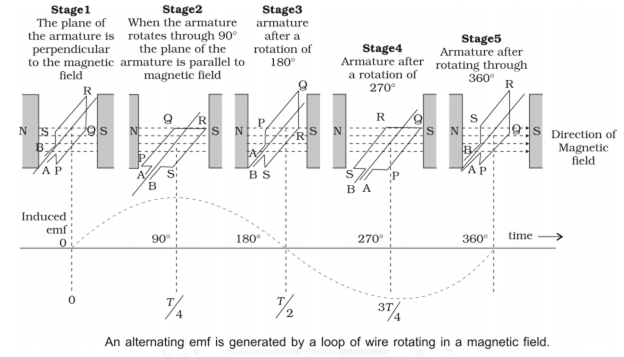
State the principle of an ac generators and explain its working with the help of a labelled diagram. Obtain the expression for the emf induced in a coil havin N turns each of cross-sectional area, rotating with a constant angular speed 'ω' in a magnetic field , directed perpendicular to the axis of rotation.
Principle − AC generator based on the phenomenon of electromagnetic induction.
Construction:
Main parts of an ac generator:
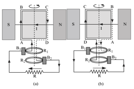
Armature − Rectangular coil ABCD
Filed Magnets − Two pole pieces of a strong electromagnet
Slip Rings − The ends of coil ABCD are connected to two hollow metallic rings R1 and R2.
Brushes − B1 and B2 are two flexible metal plates or carbon rods. They are fixed and are kept in tight contact with R1 and R2 respectively.
Theory and Working − As the armature coil is rotated in the magnetic field, angle θ between the field and normal to the coil changes continuously. Therefore, magnetic flux linked with the coil changes. An emf is induced in the coil. According to Fleming’s right-hand rule, current induced in AB is from A to B and it is from C to D in CD. In the external circuit, current flows from B2 to B1.
To calculate the magnitude of emf induced:
Suppose
A → Area of each turn of the coil
N → Number of turns in the coil
→ Strength of magnetic field
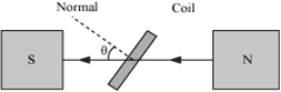
θ → Angle which normal to the coil makes with at any instant t
∴ Magnetic flux linked with the coil in this position:
= NBA cosθ= NBA cosωt …(i)
Where, ‘ω’ is angular velocity of the coil
As the coil rotates, angle θchanges. Therefore, magnetic flux Φ linked with the coil changes and hence, an emf is induced in the coil. At this instant t, if e is the emf induced in the coil, then
A coil having n turns and resistance 4R Ω. This combination is moved in time t seconds from a magnetic field W1 weber to W2 weber. The induced current in the circuit is
B.
A metal conductor of length 1 m rotates vertically about one of its ends at angular velocity 5 radians per second. If the horizontal component of earth’s magnetic field is 0.3 × 10⁻⁴ T, then the e.m.f. developed between the two ends of the conductor is
depends on the nature of the metal used
depends on the intensity of the radiation
depends both on the intensity of the radiation and the metal used
is the same for all metals and independent of the intensity of the radiation.
B.
depends on the intensity of the radiation
The emf induced between ends of conductor
The magnetic potential energy stored in a certain inductor is 25 mJ, when the current in the inductor is 60 mA. This inductor is of inductance
0.138 H
138.88 H
13.89
1.389 H
C.
13.89
Energy stored in the inductor,
U = 25 x 10-3 J
Current, I = 60 mA
Energy stored in inductor
Two similar coils are kept mutually perpendicular such that their centres coincide. At the centre, find the ratio of the magnetic field due to one coil and the resultant magnetic field through both coils, if the same current is flown.
1:3
1:2
A.
Suppose magnetic field is produced due to each coil is B.The coils are kept perpendicular hence, the angle between these is 900.
Therefore the resultant magnetic field is given by :
The primary and secondary coils of a transformer have 50 and 1500 turns respectively. If the magnetic flux linked with the primary coil is given by where is weber, t is time in second and is a constant, the output vltage across the secondary coil is
90 v
120 V
220 V
30 V
B.
120 V
The magnetic flux linked with the primary coil is given by
So voltage across primary
Also we have
NP = 50 and NS = 1500
From relation
A transformer is used to light a 100 W and 110 V lamp from a 220 V mains. If the main current is 0.5 A, the efficiency of the transformer is approximately
30%
50%
90%
10%
C.
90%
The efficiency of the transformer
Given:- Vs Is = 100 W,
Vp = 220 V,
Ip = 0.5 A
A coil of inductance 300 mH and resistance 2 0 is connected to a source of voltage 2 V. The current reaches half of its steady state value in
0.05 s
0.1 s
0.15 s
0.3 s
B.
0.1 s
The current at any instant is given by
I = Io ( 1 - e-R t /L )
e-Rt/L = 1/ 2
When power is drawn from the secondary coil of the transformer, the dynamic resistance
increases
decreases
remains unchanged
changes erratically
A.
increases
When the secondary coil circuit is open, the magnetic flux in the core is produced by the primary current only. When the secondary circuit is closed, the currents in the secondary coil also produce the magnetic flux in the core but in opposite direction. This decreases the core flux and hence reduces the back emf produced in the primary coil.
The source emf is now in excess of the back emf, more current is drawn in the primary coil. Hence, the power factor is no longer zero. The power factor has increased or the phase difference is no longer 90°, ie, phase difference has decreased. Thus, dynamic resistance has increased.
The magnetic flux linked with a coil at any instant t is given by the equation . The magitude of emf induced in coil after 3 s is
10 V
20 V
35 V
70 V
C.
35 V
Given:-
=
=
= 15 t2 + 100
= -135 + 100
Sponsor Area
In 0.1 s, the current in a coil increases from 1 A to 1.5A. If inductance of coil is 60 mH, then induced current in external resistance of 32 will be
1 A
0.5 A
0.2 A
0.1 A
D.
0.1 A
The magnitude of induced emf in a circuit is equal to the inductance × rate of current change and a circuit has an inductance of one Henry will have one volt induced in the circuit when the circuit changes at a rate of one ampere per second.
When a current in coil changes, it induces a back emf in the same coil. The self-induced emf is given by
Induced emf,
=
0.3 V
Induced current,
i =
=
i = 0.1 A
In 0.2 s, the current in a coil increases from 2.0 A to 3.0 A. If inductance of coil is 60 mH, then induced current in external resistance of 3 Ω will be
1A
0.5 A
0.2 A
0.1 A
D.
0.1 A
When a current in a coil changes, it induces a back emf back emf in the same coil. The self-induced emf is given by
Induced emf
=
=
= 0.3 A
A changing magnetic field through a coil of wire therefore must induce an emf in the coil which in turn causes current to flow.
Induced current
i =
=
i = 0.1 A
A transformer having efficiency of 75 % is working on 220 V and 4.4 kW power supply. If the current in the secondary coil is 5 A. What will be the voltage across secondary coil and the current in primary coil?
Vs = 220 V, ip = 20A
Vs = 660 V, ip = 15 A
Vs = 660 V, ip = 20 A
Vs = 220 V, ip = 15 A
C.
Vs = 660 V, ip = 20 A
Given:- Pin = 4.4 kW,
Vp = 220 V,
is = 5A,
Vs = ?
We know that
iP =
=
ip = 20A
∴ Efficiency,
Percentage efficiency
η =
75% = 100 ×
Pout =
= 3300 W
∴ Pout = VS. iS
⇒ VS =
⇒ VS = 660 V
A cylinder of radius R and length L is placed in a uniform electric field E parallel to the cylinder axis. The total flux for the surface of the cylinder is given by
2R2 E
Zero
D.
Zero
Flux through surface A
Flux through curved surface
C =
= cos90o
C = 0
Total flux through cylinder =
= 0
In the given figure what will be the coefficient of mutual inductance
C.
Magnetic field due to wire
B =
dA = a dx
and d = B. dA
On integrating both sides, we get
⇒
=
=
=
= M i
Where M = coefficient of mutual inductance
and M =
The total charge induced in a conducting loop when it is moved in magnetic field depends on
the rate of change of magnetic flux
initial magnetic flux only
the total change in magnetic flux
final magnetic flux only
C.
the total change in magnetic flux
The induced emf is produced due to change in magnetic flux in the coil.
Induced emf is given by
e =
As
i =
=
∴ Total charge induced =
= dt
=
=
Thus, the induced charge in a conducting loop, moving in a magnetic field depends on the total change in magnetic flux.
For MRI, a patient is slowly pushed in a time of 10 s within the coils of the magnet where magnetic field is B = 2.0 T. If the patient's trunk is 0.8 m in circumference, the induced emf around the patient's trunk is
10.18 x 10⁻² V
9.66 × 10² V
10.18 × 10⁻³ V
1.51 × 10⁻² V
C.
10.18 × 10⁻³ V
Change in magnetic field in 10 s = 2.0 T
As
ε =
= ( = BA )
Circumference of patient's trunk
2 r = 0.8 m (given)
∴ r = m
r = m
Area of cross section
A =
A =
A = m2
∴ V
≈ 10.18 × 10⁻³ V
The self-inductance of a coil having 400 turns is 10 mH. The magnetic flux through the cross-section of the coil corresponding to current 2 mA is
2 × 10⁻⁵ Wb
2 × 10⁻³ Wb
3 × 10⁻⁵ Wb
8 × 10⁻³ Wb
A.
2 × 10⁻⁵ Wb
Number of turns N = 400
L = 10 mH = 10 × 10-3 H
I = 2 mA = 2 × 10⁻³ A
Total magnetic flux linked with the coil,
= N L I
= 400 × ( 10 × 10-3 ) × 2 × 10-3
= 8 × 10⁻³ Wb
Magnetic flux through the cross-section of the coil = Magnetic flux linked with each turn
=
= 2 × 10⁻⁵ Wb
A coil of inductance 8 μH is connected to a capacitor of capacitance 0.02 μF To what wavelength is this circuit tuned?
7.54 × 10³ m
4.12 × 10² m
15.90 × 10³ m
7.54 × 10² m
D.
7.54 × 10² m
L = 8 μH = 8 × 10⁻⁶ H
C = 0.02 μF = 0.02 × 10⁻⁶ F
∴ Resonant frequency
fr =
=
fr = 3.98 × 10⁵ Hz
If c ( = 3 × 10⁸ m s-1 ) is the velocity of the electromagnetic wave, then
Wavelength
λ =
=
λ = 7.54 × 10² m
Assertion: An emf E is induced in a closed loop when magnetic flux is varied. The induced electric field E is not a conservative field.
Reason: The line integral around the closed loop is non-zero.
If both assertion and reason are true and reason is the correct explanation of assertion.
If both assertion and reason are true but reason is not the correct explanation of assertion.
If assertion is true but reason is false.
If both assertion and reason are false.
A.
If both assertion and reason are true and reason is the correct explanation of assertion.
We know
ε =
=
As ≠ 0
the induced electric field is non-conservative in nature.
Sponsor Area
Sponsor Area