

Sponsor Area
Electromagnetic Induction
State the principle of an ac generators and explain its working with the help of a labelled diagram. Obtain the expression for the emf induced in a coil havin N turns each of cross-sectional area, rotating with a constant angular speed 'ω' in a magnetic field , directed perpendicular to the axis of rotation.
Principle − AC generator based on the phenomenon of electromagnetic induction.
Construction:
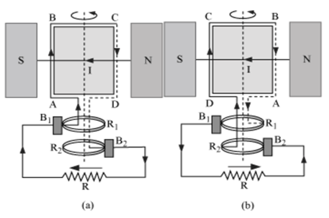
Main parts of an ac generator:
-
Armature − Rectangular coil ABCD
-
Filed Magnets − Two pole pieces of a strong electromagnet
-
Slip Rings − The ends of coil ABCD are connected to two hollow metallic rings R1 and R2.
-
Brushes − B1 and B2 are two flexible metal plates or carbon rods. They are fixed and are kept in tight contact with R1 and R2 respectively.
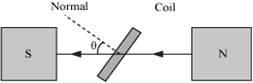
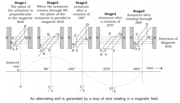
Theory and Working − As the armature coil is rotated in the magnetic field, angle θ between the field and normal to the coil changes continuously. Therefore, magnetic flux linked with the coil changes. An emf is induced in the coil. According to Fleming’s right-hand rule, current induced in AB is from A to B and it is from C to D in CD. In the external circuit, current flows from B2 to B1.
To calculate the magnitude of emf induced:
Suppose
A → Area of each turn of the coil
N → Number of turns in the coil
→ Strength of magnetic field
θ → Angle which normal to the coil makes with ![]() at any instant t
at any instant t
∴ Magnetic flux linked with the coil in this position:
= NBA cosθ= NBA cosωt …(i)
Where, ‘ω’ is angular velocity of the coil
As the coil rotates, angle θchanges. Therefore, magnetic flux Φ linked with the coil changes and hence, an emf is induced in the coil. At this instant t, if e is the emf induced in the coil, then


An aeroplane is flying horizontally from west to east with a velocity of 900 km/hour. Calculate the potential difference developed between the ends of its wings having a span of 20 m. The horizontal component of the Earth’s magnetic field is 5 × 10⁻⁴ T and the angle of dip is 30°.
e = Bv.V.l
=
An inductor of inductance L = 400 mH and resistors of resistances R1 = 2 Ω and R2 = 2 Ω is connected to a battery of emf 12 V as shown in the figure. The internal resistance of the battery is negligible. The switch S is closed at t = 0. The potential drop across L as a function of time is 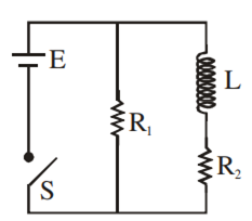
-
6e–5t V
-

-

-
12e–5t V
D.
12e–5t V

Two identical conducting wires AOB and COD are placed at right angles to each other. The wire AOB carries an electric current I1 and COD carries a current I2. The magnetic field on a point lying at a distance ‘d’ from O, in a direction perpendicular to the plane of the wires AOB and COD, will be given by


B.

Sponsor Area
Mock Test Series
Mock Test Series