

Sponsor Area
Junction Transistors
Figure below shows the circuit of an electronic device:
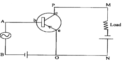
(i) Which electronic device: a rectifier, an amplifier or an oscillator does the above circuit represent?
(ii) State where the input voltage is applied and where the output voltage is available.
(iii) Compare the output voltage of this circuit with its input voltage.
(i) Amplifier
(ii) Input voltage is applied across AB, output voltage is obtained across the road.
(iii) Output voltage = 50 x input voltage
That is, input voltage is 50 times the output voltage.


A sinusoidal voltage e = e0 Sin (wt) is fed to a common emitter amplifier. Draw neatly labelled diagrams to show:
(i) Signal voltage
(ii) Output voltage of the amplifier.
Common emitter n-p-n transistor Amplifier:
Signal voltage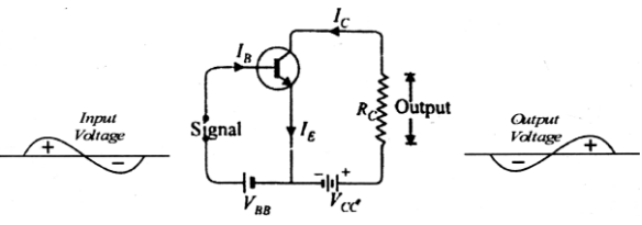
Common emitter p-n-p transitor Amplifier:
Output voltage of the ampifier: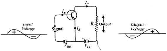
Draw a labelled circuit diagram of a N-P-N transistor in a common-emitter configuration to study its characteristics.
Labelled circuit diagram of an N-P-IV transistor in a common-emitter configuration is given below: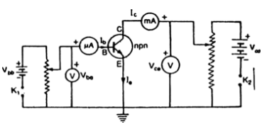
Draw the circuit diagram of a half-wave rectifier using a p-n junction diode.

Sponsor Area
Mock Test Series
Mock Test Series